
Related Manuals for Cell2 SDF104H

Summary of Contents for Cell2 SDF104H
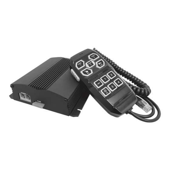
- Page 1 SDF104H Siren Amplifier Installation & Operation Manual NOTICE TO INSTALLER Before installation and operation ― read all instructions and warnings. Deliver this manual to the end user of this product.
-
Page 3: Table Of Contents
3. Failure to follow these instructions could result in serious damage to the unit or vehicle and may void warranties. 4. The correct mounting and wiring is the key to the effectiveness of SDF104H. 5. Installers must read and follow instructions and warnings in the manual from the original manufacturer. -
Page 4: Contents
Extension cable x 1 pc (4m) RJ45 coupler x 1 pc Accessory SDF104H Siren Amplifier Installation & Operation Manual NOTICE TO INSTALLER Before installation and operation ― read all instructions and warnings. -
Page 5: Wiring
WIRING ● Wiring diagram: (Fuse Rating: 35 A @ 12-24VDC; user-supplied) – Power +VDC – Power -GND Connector A Battery Controller RJ45 Connector Connector B w/ Extension Cable RED – IGNITION ACTIVATION (+Ve) ORANGE – SW1 (Load 5 Amps Max.) YELLOW –... - Page 6 Power Wire Terminal Block (Connector A) ● Power +VDC & -GND 1. Connect to the positive (+) battery terminal. Fuse each wire independently @35 Amps (user-supplied). DO NOT install these fuses until the wiring for the entire system has been completed. 2.
-
Page 7: Controller Function
CONTROLLER FUNCTION Before any operation, apply positive voltage to the IGN (Ignition) wire at the rear to power-up the unit. Button Decal PTT: Activate Microphone for PA Broadcast through the siren speaker. This Button overrides all other acoustic function (i.e. Air Horn, Siren Tone and Radio Rebroadcast) while it is activated. - Page 8 3. Once set, press PTT and HORN buttons for 5 seconds to save and exit Tone Cycle Setting. Code 2 will stop blinking to indicate that you have exited. INDICATION CHART: TONE CYCLE COUNTRY TONE FREQUENCY CYCLE/MINUTE RADIO SW3 (Hz) 761-1592 WAIL 12 C/M INTERNATIONAL...
- Page 9 Volume Adjustment PA, Siren and Radio Re-broadcasting may be set to different INDICATION CHART Volume Level (total of 8 levels, default at 8). 1. Press and hold PTT, MAN and Code 1 for 5 seconds to enter Volume Adjustment Setting. 2.
- Page 10 Code Button Combo Setting Code 1, Code 2 and Code 3 buttons may be programmed to turn on and off switch button controls (SW1~SW4) and/or SIREN button together. 1. Press and hold PTT, MAN and RADIO for 5 seconds to enter Code Button Combo Setting. RADIO will blink to indicate that you are in Code Button Combo Setting.
-
Page 11: Installation
INSTALLATION Mounting ● Siren amplifier 1. Select a location that is not exposed directly to weather elements, such as the driver compartment firewall, below the seat, or in the trunk; avoid any interference of air bag deployment. 2. Using the siren amplifier as a template, mark four mounting holes to be drilled. 3. - Page 12 86-S00810-0101.1...
Need help?
Do you have a question about the SDF104H and is the answer not in the manual?
Questions and answers