Table of Contents
Advertisement
Quick Links
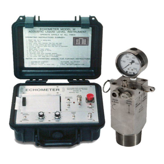
Digital Dual Channel Fluid Level Instrument
Introduction
This operating manual contains information about the Echometer Model M Fluid Level Instrument including operating
procedures, maintenance, shooting problem wells, chart interpretation and technical papers relating to the optimization
of producing wells. Please read the first 25 pages and view the example of the strip chart output forms and charts on
wells before operating the instrument. Additional technical papers can be accessed from the Echometer Web page,
www.echometer.com, these articles offer additional information on the use of acoustic fluid level instruments to
optimize production. Please read these papers at your convenience.
Limits of Liability
Echometer Company reserves the right to revise its software and publications with no obligation of Echometer
Company to notify any person or any organization of such revision. In no event shall Echometer Company be
liable for any loss of profit or any commercial damage, including but not limited to special, consequential, or other
damages.
Information in this document is subject to change without notice and does not represent a commitment on the part
of Echometer Company. The software described in this document is furnished under a license agreement or
nondisclosure agreement. It may be used or copied only in accordance with the terms of the agreement. It is
against the law to copy the software or any medium except specifically allowed in the license or non-disclosure
agreement.
Copyright Notice
Copyright 1997,1998,1999,2000,2001,2002,2003 Echometer Company. All rights reserved. Federal copyright
law protects this manual. No part of this manual may be copied or distributed, transmitted, transcribed, stored in a
retrieval system or translated into any human or computer language, in any form or by any means, electronic,
mechanical, magnetic, manual, photographic, photocopy, scanning, or otherwise, or disclosed to third parties
without the express written permission of Echometer Company.
Trademarks
AWP, TWM, QRod, EchoPUMP, Compact Gas Gun are trademarks of Echometer Company
Echometer Company
5001 Ditto Lane
Wichita Falls, Texas 76302, U.S.A.
Echometer Model-M
Model – M Manual
Page 1
Phone: (940) 767-4334
Fax: (940) 723-7507
E-Mail:
info@echometer.com
Advertisement
Table of Contents

Subscribe to Our Youtube Channel
Related Manuals for Echometer M


Summary of Contents for Echometer M
-
Page 1: Introduction
Echometer Company reserves the right to revise its software and publications with no obligation of Echometer Company to notify any person or any organization of such revision. In no event shall Echometer Company be liable for any loss of profit or any commercial damage, including but not limited to special, consequential, or other damages. -
Page 2: Table Of Contents
General Recording Procedure ......................15 Operation of the Model M with the Compact Gas Gun ..............16 Operation of the Model M with the Remote Fired Gas Gun ............17 Recommendations for Optimum Performance................. 18 Automatic Gain Setting (AGS) Mode Characteristics ..............19 Manual Gain Setting (MGS) Mode Characteristics ................. - Page 3 FIGURE 1a - COMPACT GAS GUN ASSEMBLY DRAWING ..........28 FIGURE 1b - REMOTE FIRE GAS GUN ASSEMBLY DRAWING ........... 29 FIGURE 2 - ECHOMETER PANEL ....................30 FIGURE 3 – INITIAL HEADER AND SYSTEM TEST (SHOWN ½ SCALE) ......30 FIGURE 4 –...
-
Page 4: Safety Considerations
Echometer Schools Echometer Company offers schools on the use and applications of this equipment. You are invited to attend free of charge. A list of the schools, which are taught throughout the United States and Canada, will be sent upon request or can be viewed at http://www.Echometer.com... -
Page 5: 2-Principles Of Acoustic Measurements
Fluid level instruments are designed to include various filters, which can be used to accent signals that correspond to these frequency ranges. The Model M records the signal on the dual channels. One channel is tuned to higher frequencies from the collars while the second channel is tuned to low frequencies from the liquid level. -
Page 6: Depth Calculation
The acoustic instruments can be used to measure the distance to any change in cross-sectional area inside pipe or in the annulus. Echometer Company Phone: (940) 767-4334 Model – M Manual 5001 Ditto Lane Page 6 Fax: (940) 723-7507 Wichita Falls, Texas 76302, U.S.A. -
Page 7: General Description - Model M
(orreduction in annulus area) is opposite to the response from an enlargement such as a hole in the casing. The Model M uses modern electronics, integrated circuits, chart drive system and a thermal printhead, which result in a very compact and lightweight system. -
Page 8: Instrument Panel
Depressing this switch operates the solenoid valve on a remote fired gas gun by applying 12 volts to the solenoid coil. Depress the switch for 1 second to fully release gas from the chamber. Echometer Company Phone: (940) 767-4334 Model – M Manual 5001 Ditto Lane Page 8 Fax: (940) 723-7507 Wichita Falls, Texas 76302, U.S.A. -
Page 9: Wellhead Attachments
The paper is dropped into the cavity so that it unrolls counter-clockwise. After inserting the paper roll, the aluminum cover is replaced. The printed Echometer logo on the paper should face up since only this side of the paper is heat sensitive. The heat sensitive paper supplied by Echometer Company operates over a wide temperature range and is made for the Echometer Chart drive system. - Page 10 Microphone The microphone is a twin-disc pressure sensitive device that is vibration canceling. Echometer Company Phone: (940) 767-4334 Model – M Manual 5001 Ditto Lane Page 10 Fax: (940) 723-7507 Wichita Falls, Texas 76302, U.S.A.
-
Page 11: Remote Fire Gas Gun
100-psi in excess of casing pressure unless additional pressure is required to obtain desire results. Echometer Company Phone: (940) 767-4334 Model – M Manual 5001 Ditto Lane Page 11 Fax: (940) 723-7507 Wichita Falls, Texas 76302, U.S.A. -
Page 12: High Pressure Gas Guns
The casing pressure and casing pressure buildup during the acoustic test must be measured with an accurate and sensitive pressure gauge or sensor. The Remote Fire Gas Gun supplied with the Echometer Model M is equipped with a quick connect gauge that covers the range 0-200 psig. The user should consider the option of obtaining several gauges covering different pressure ranges. -
Page 13: Model M Modifications And Enhancements
Universal Coordinated Time Zone in England. The date and time on the enhanced Model M are set as follows. There are two small holes located in the lower panel to the left of the input connector. - Page 14 Remote Fire Gas Gun When both collar and liquid level gain controls are set to the “AUTO” position, the Model M will automatically provide a fire signal to the Remote Fire Gas Gun after the chart drive is turned ON.
-
Page 15: Operation
The upper record is with the filter setting on upper collars and the lower record shows the response when the filter setting is lower collars. Echometer Company Phone: (940) 767-4334 Model – M Manual 5001 Ditto Lane Page 15 Fax: (940) 723-7507 Wichita Falls, Texas 76302, U.S.A. -
Page 16: Operation Of The Model M With The Compact Gas Gun
COMPRESSION (EXPLOSION) MODE Expansion of gas from the Echometer gas gun is used to generate a pressure pulse. The pressure pulse is positive since the gas chamber is charged to a pressure that exceeds the well pressure by at least 100-psi. -
Page 17: Operation Of The Model M With The Remote Fired Gas Gun
Verify that the volume chamber pressure is at least 100-psi in excess of the Casing Pressure. Connect the coaxial cable from the microphone to the Input of the Model M. 10. Connect the remote fire cable from the gun to the REMOTE FIRE connector. -
Page 18: Recommendations For Optimum Performance
Recommendations for Optimum Performance The Echometer wellhead should be as near as possible to the casing annulus (or the tubing) preferably within 5 feet. Short (5-10 ft) lengths of pipe can mask the desired downhole signals. Longer (20-60 ft) lengths will generate multiple reflections, which are hard to distinguish from collar reflections. -
Page 19: Automatic Gain Setting (Ags) Mode Characteristics
Automatic Gain Setting (AGS) Mode Characteristics The Echometer Model M uses a microprocessor, which is programmed to evaluate the signal level before the shot and set the amplifier gain as necessary to optimize the quality of the recording. The AGS mode on either or both channels is activated by selecting the AUTO position before the chart drive is turned ON. -
Page 20: Interpretation
When the wave passes from the narrow liner to the larger casing a portion of the wave is converted to a rarefaction pulse, which then travels down to the liquid level and then to the surface where it is recorded. Echometer Company Phone: (940) 767-4334 Model – M Manual 5001 Ditto Lane Page 20 Fax: (940) 723-7507 Wichita Falls, Texas 76302, U.S.A. -
Page 21: Problem Wells
In extreme cases it may be necessary to clean the tubing and casing to remove the foreign material. Echometer Company Phone: (940) 767-4334 Model – M Manual 5001 Ditto Lane Page 21 Fax: (940) 723-7507 Wichita Falls, Texas 76302, U.S.A. -
Page 22: Battery And External Power Information
12-volt battery. A sealed, rechargeable, lead cell, 2.5 amp/hour internal battery is used in the Echometer Model M instrument. The battery is similar to a 12 volt sealed automobile battery. The battery charger provided with the unit permits charging the battery from an AC power outlet. -
Page 23: Important Notes And Instructions For Rechargeable Batteries
Important Notes and Instructions for Rechargeable Batteries The battery is rated at 2.5 Amp-Hour. The Model M current drain with the chart drive on is 1 Amp. Thus the battery operating ON-time is approximately 2.5 hours and the unit would use about five rolls of paper. -
Page 24: Testing/Troubleshooting
8 - Testing/Troubleshooting The Echometer Model - M has an internal test circuit, which is used to verify that the electronics and the acoustic cable are operating correctly. The test circuit is activated automatically when the power is turned ON. A system test and battery voltage is displayed on the strip chart. -
Page 25: Maintenance
9 - Maintenance The Echometer Model –M instrument should be kept clean. The battery should be kept charged as described by the instructions in Section 7. Do not subject the unit to shock loads. Using the Compact Gas Gun or the Remote Fire Gas Gun in the EXPLOSION mode (the preferred mode of operation) will require minimum maintenance. -
Page 26: Remote Fire Gas Gun Pressure Rating
Replace the "O" rings as needed. All other connectors, ports, and the solenoid valve can be serviced without need to remove the volume chamber. Echometer Company Phone: (940) 767-4334 Model – M Manual 5001 Ditto Lane Page 26 Fax: (940) 723-7507 Wichita Falls, Texas 76302, U.S.A. -
Page 27: Calculation Of Bottomhole Pressures
Bottomhole pressure calculation in static and producing wells is described in technical papers and is facilitated by the use of software, which is supplied with the Echometer Model M. Details of the calculation methods used by the software are found in technical papers on the internet at www.echometer.com... -
Page 28: Appendix
11 – APPENDIX FIGURE 1a - COMPACT GAS GUN ASSEMBLY DRAWING Echometer Company Phone: (940) 767-4334 Model – M Manual 5001 Ditto Lane Page 28 Fax: (940) 723-7507 Wichita Falls, Texas 76302, U.S.A. E-Mail: info@echometer.com... - Page 29 FIGURE 1b - REMOTE FIRE GAS GUN ASSEMBLY DRAWING Echometer Company Phone: (940) 767-4334 Model – M Manual 5001 Ditto Lane Page 29 Fax: (940) 723-7507 Wichita Falls, Texas 76302, U.S.A. E-Mail: info@echometer.com...
- Page 30 Panel shown is serial number 4999 and below. FIGURE 2 - ECHOMETER PANNEL On units above serial number 5000, the test traces at left are replaced by notation of SELF TEST PASS or FAIL. FIGURE 3 – INITIAL HEADER AND SYSTEM TEST (SHOWN ½ SCALE) FIGURE 4 –...
- Page 31 FIG. 5 – UPPER/LOWER COLLARS ACCENTED Echometer Company Phone: (940) 767-4334 Model – M Manual 5001 Ditto Lane Page 31 Fax: (940) 723-7507 Wichita Falls, Texas 76302, U.S.A. E-Mail: info@echometer.com...
- Page 32 FIG. 6 – PROVE LIQUID LEVEL Echometer Company Phone: (940) 767-4334 Model – M Manual 5001 Ditto Lane Page 32 Fax: (940) 723-7507 Wichita Falls, Texas 76302, U.S.A. E-Mail: info@echometer.com...
- Page 33 Fig. 7 – WELL WITH LINER Echometer Company Phone: (940) 767-4334 Model – M Manual 5001 Ditto Lane Page 33 Fax: (940) 723-7507 Wichita Falls, Texas 76302, U.S.A. E-Mail: info@echometer.com...
- Page 34 FIG. 8 – RECORDS OF COMPRESSION/RAREFACTION INITIAL PULSE Echometer Company Phone: (940) 767-4334 Model – M Manual 5001 Ditto Lane Page 34 Fax: (940) 723-7507 Wichita Falls, Texas 76302, U.S.A. E-Mail: info@echometer.com...
-
Page 35: Acoustic Responses From Downhole Anomalies
Thus, the response from these anomalies will be upward when the top of the chart is to the operator’s left. Echometer Company Phone: (940) 767-4334 Model – M Manual 5001 Ditto Lane Page 35 Fax: (940) 723-7507 Wichita Falls, Texas 76302, U.S.A. -
Page 36: Amplifiers And Filters Test
Amplifiers And Filters Test On Model M Recorders having serial numbers above 5100, the amplifiers and filters are checked automatically. After the power switch is turned on and the test has been performed, the message PASS or FAIL is recorded onto the strip chart. On units below serial number 5100, the amplifiers and filters are checked each time that the POWER switch is turned ON. -
Page 37: Microphone Cable Test
On Model M Recorders having serial numbers above 5100, the microphone cable is tested in conjunction with the microphone test as described on the next page. On Model M Recorders having a serial number below 5100, the microphone cable can be tested using a special TEST circuit and TEST connector on the panel of the instrument. First, the Amplifier and Filter Check should be performed to insure that the electronics, chart drive and printhead are performing properly. -
Page 38: Microphone Test
Turn the Power Switch ON. Set the filter switch to LOWER COLLARS. After the chart drive stops, turn the Chart Drive Switch ON. Squeeze the test bulb. Hold for approximately 1 second, and then release the test bulb. The response should be similar to the examples below. MODEL M SERIAL NO. BELOW 5100 ABOVE 5100... -
Page 39: Rate Of Fill-Up Graph
” tubing and 4 ” casing, producing at 700 BPD will have an initial fill-up rate of 59 feet per minute. Echometer Company Phone: (940) 767-4334 Model – M Manual 5001 Ditto Lane Page 39 Fax: (940) 723-7507 Wichita Falls, Texas 76302, U.S.A. -
Page 40: Use Of Rate Of Fill-Up Information
A casing pressure build-up rate in excess of 1 PSI in three minutes indicates that the casing annulus liquid contains a substantial amount of free gas and the fill-up data should be used with caution. Echometer Company Phone: (940) 767-4334 Model – M Manual 5001 Ditto Lane Page 40 Fax: (940) 723-7507 Wichita Falls, Texas 76302, U.S.A. -
Page 41: Carbon Dioxide Cylinder
See details in operating manual. Have Cylinder pressure checked or replaced two years from date of purchase. Echometer Company Phone: (940) 767-4334 Model – M Manual 5001 Ditto Lane Page 41 Fax: (940) 723-7507 Wichita Falls, Texas 76302, U.S.A. E-Mail:... -
Page 42: Carbon Dioxide Information
Specific Volume @ 70 F, 1-atm 8.76 cu ft/lb or 15,000 cu in/lb or 950 cu in/oz Echometer Company Phone: (940) 767-4334 Model – M Manual 5001 Ditto Lane Page 42 Fax: (940) 723-7507 Wichita Falls, Texas 76302, U.S.A. E-Mail: info@echometer.com... -
Page 43: Nitrogen Information (N 2 )
Critical Pressure 492.45-psia (33.5-atm) Specific Volume @ 70 F, 1-atm 13.8 cu ft/lb or 31,000 cu in/lb Echometer Company Phone: (940) 767-4334 Model – M Manual 5001 Ditto Lane Page 43 Fax: (940) 723-7507 Wichita Falls, Texas 76302, U.S.A. E-Mail: info@echometer.com... - Page 44 FIG. 9 – CO2 CYLINDER W/ HOSE Echometer Company Phone: (940) 767-4334 Model – M Manual 5001 Ditto Lane Page 44 Fax: (940) 723-7507 Wichita Falls, Texas 76302, U.S.A. E-Mail: info@echometer.com...
- Page 45 FIG. 10 –Filler Connector for 7.5 OZ. CO2 CYLINDER Echometer Company Phone: (940) 767-4334 Model – M Manual 5001 Ditto Lane Page 45 Fax: (940) 723-7507 Wichita Falls, Texas 76302, U.S.A. E-Mail: info@echometer.com...
Need help?
Do you have a question about the M and is the answer not in the manual?
Questions and answers