Table of Contents
Advertisement
DGP000814AAA
Issue: 2-01
July 2007
GSS6100 AND SIMCHAN USER MANUAL
PROPRIETARY INFORMATION
THE INFORMATION CONTAINED IN THIS DOCUMENT IS THE PROPERTY OF SPIRENT
COMMUNICATIONS PLC. EXCEPT AS SPECIFICALLY AUTHORISED IN WRITING BY SPIRENT
SPIRENT COMMUNICATIONS PLC, THE HOLDER OF THIS DOCUMENT SHALL KEEP ALL
INFORMATION CONTAINED HEREIN CONFIDENTIAL AND SHALL PROTECT SAME IN WHOLE OR IN
PART FROM DISCLOSURE AND DISSEMINATION TO ALL THIRD PARTIES TO THE SAME DEGREE IT
PROTECTS ITS OWN CONFIDENTIAL INFORMATION.
© SPIRENT COMMUNICATIONS PLC 2005-2007
Advertisement
Chapters
Table of Contents

Subscribe to Our Youtube Channel
Related Manuals for Spirent GSS6100


Summary of Contents for Spirent GSS6100
- Page 1 July 2007 GSS6100 AND SIMCHAN USER MANUAL PROPRIETARY INFORMATION THE INFORMATION CONTAINED IN THIS DOCUMENT IS THE PROPERTY OF SPIRENT COMMUNICATIONS PLC. EXCEPT AS SPECIFICALLY AUTHORISED IN WRITING BY SPIRENT SPIRENT COMMUNICATIONS PLC, THE HOLDER OF THIS DOCUMENT SHALL KEEP ALL...
- Page 3 GSS6100 signal generator using both SimCHAN software and the remote command set. Audience This document is intended for all users of the GSS6100 signal generator and SimCHAN software. In this document: References to Spirent refer to Spirent Communications - Performance Analysis &...
- Page 5 CHAN INTERFACE 4.2.1 Controlling the GSS6100 ................4-3 4.2.2 Help ........................ 4-3 4.2.3 Status bar ....................... 4-3 CHAPTER 5: GSS6100 OPERATING DETAILS ................5-1 CHAN TOOLBAR 5.1.1 ARM the GSS6100 ..................5-2 5.1.2 RUN the GSS6100 ..................5-3 5.1.3 HALT the GSS6100 ..................5-3...
- Page 6 G2D ......................6-17 6.2.29 SIGT ......................6-18 6.2.30 SNUM ? ......................6-18 6.2.31 STAT ......................6-18 6.2.32 SVID ......................6-19 6.2.33 TIOP ......................6-19 6.2.34 TIOP ? ......................6-20 6.2.35 TRIG ......................6-20 6.2.36 VCTY ......................6-21 GSS6100 and SimCHAN user manual Contents © Spirent Communications Plc 2005 - 2007...
- Page 7 Data Fields ....................G-2 APPENDIX H: SBAS CORRECTION DATA FILES...............H-1 SBAS REATING AND EDITING A CORRECTION DATA FILE H.1.1 Example ......................H-2 H.1.2 Default *.WAS file, WAAS_DEF.WAS............H-2 GSS6100 and SimCHAN user manual © Spirent Communications Plc 2005 - 2007 Contents...
- Page 8 Possible *.WAS data errors................H-23 APPENDIX I: PRODUCT SAFETY AND COMPLIANCE.............. I-1 AFETY NOTICE AND SAFETY COMPLIANCE APPENDIX J: SPECIAL NAV DATA TEMPLATE................J-1 APPENDIX K: CONTACTING SPIRENT CUSTOMER SUPPORT ..........I INDEX LIST OF FIGURES LIST OF TABLES VIII GSS6100 and SimCHAN user manual Contents ©...
- Page 9 July 2007 Bugz: 3122: Added pin-out table for 1PPS IN / OUT. 3238: Added NMOD command and details on special NAV templates 3586: Updated contact details. GSS6100 and SimCHAN user manual © Spirent Communications Plc 2005 - 2007 General...
- Page 10 InstallShield is a registered trademark of InstallShield Software Corporation. All other company/product names referenced herein are trademarks and/or service marks or registered trademarks and/or service marks of their respective holders. GSS6100 and SimCHAN user manual General © Spirent Communications Plc 2005 - 2007...
- Page 11 A standard interface commonly supplied for portable computers. Also known as PC Card it is Hot Pluggable enabling devices to be added/removed as needed. Parts Per Million GSS6100 and SimCHAN user manual © Spirent Communications Plc 2005 - 2007 General...
- Page 12 Acronym for the Operating System used with DEC Alpha Workstations. eXtensible Markup Language – a standard syntax and semantics for passing information between computers as a text based vendor independent file. GSS6100 and SimCHAN user manual General © Spirent Communications Plc 2005 - 2007...
- Page 13 This document refers to: Buttons, such as Clear, with Bold text. Filenames, such as GSS6100.ini, with Bold italic text. Text boxes, such as Velocity (m/sec) with Bold text. You enter data values by typing the value in the text box, which is referred to by its name, for example Pseudo Range Velocity –...
- Page 14 1.5.1.2 Hardware This document refers to: The GSS6100 as a signal generator. “Operating” the GSS6100 to produce an RF signal. GSS6100 and SimCHAN user manual General © Spirent Communications Plc 2005 - 2007...
- Page 15 Spirent, world leaders in the field of Satellite Navigation Systems Simulation. The GSS6100 is a precision, stand-alone, single-channel, L1 C/A code GPS signal generator that uses the SimCHAN control software. Typically the GSS6100 is used to evaluate GPS/SBAS receivers and applications for the...
-
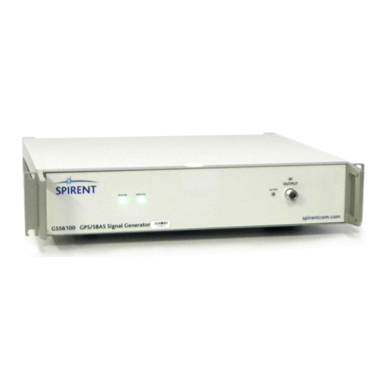
Page 17: Table 3-1 Front Panel Indicators And Connector
Spirent Specification, reference g), gives full details of the connectivity and signals produced by the GSS6100, together with environmental information. Front panel Figure 3-1 shows the GSS6100 front panel. Table 3-1describes the front panel indicators and connector. Figure 3-1 GSS6100 front panel... - Page 19 2-01 DGP000814AAA REAR PANEL Figure 3-2 GSS6100 rear panel Made in U.K. MODEL: GSS6100 S/N: XXXX GSS6100 and SimCHAN user manual © Spirent Communications Plc 2005 - 2007 Hardware overview and installation...
-
Page 20: Table 3-2 Rear Panel Connectors
-0.5 V < Low < +0.8 V +2.0 V < High < +5.5 V 50 Ω input impedance Section 5.6 shows timing details. EXT REF IN Locks the GSS6100 to an external frequency reference. 10 MHz OUT Internal OCXO reference output. HOST (USB) USB downstream connector Control and data connection to the host PC. -
Page 21: Table 3-3 1 Pps In / Out 25 Way Connector Pin-Out
1 In combination with the External Reference input, 1PPS IN can be used to synchronise the simulator to an external system, see Section 5.6, TTL level compatible. 2 TTL level compatible, nominal pulse width 100ms GSS6100 and SimCHAN user manual © Spirent Communications Plc 2005 - 2007 Hardware overview and installation... - Page 22 Apply ac power to the GSS6100 and switch it on. Note: The power input to the GSS6100 is auto sensing for 100-120V or 220- 240V operation. After a brief power-up sequence, the POWER and HEALTH LEDs on the GSS6100front panel illuminate continuously to show correct operation.
- Page 23 Once you have set these attributes, the GSS6100 must be set into the Arm state. The Arm state is an interim step prior to setting the GSS6100 into the Run state. The Arm state configures the GSS6100 and allows you to make any final adjustments to certain parameter types.
- Page 24 DGP000814AAA 2-01 SimCHAN interface SimCHAN lets you set and adjust in real time, the operating parameters of the GSS6100. It also displays messages. SimCHAN has three main areas, see Figure 4-1: The menu and tool bar. The main area. The status bar.
- Page 25 4.2.2 Help The Help menu lets you select HTML format versions of the GSS4100 user manual and the GSS6100 user manual. You can also press F1 to open the Help menu. Click on About to see details on the GSS6100 signal generator connected to the PC and the version of SimCHAN.
-
Page 27: Table 5-1 Parameter Section References
2-01 DGP000814AAA Chapter 5: GSS6100 operating details All parameter settings you apply to the GSS6100 are written to a file. You can save this parameter file using the File menu. The default parameter file extension is .gss. A parameter file can be loaded before SimCHAN runs. Using a parameter file lets you easily and quickly run the GSS6100 in a known state. - Page 28 5.1.1 ARM the GSS6100 [Remote Command: ARMS see section 6.2.3] Figure 5-2 ARM button Click ARM to load the selected parameters to the GSS6100 and to prepare for a run. The Status bar shows ‘Ready to Run’ when the arming sequence is complete.
- Page 29 Click HALT to abort the operation in progress or terminate the Ready to Run state. After you click HALT, SimCHAN and the GSS6100 return to the Idle state. You can HALT the operation to change parameters. The time at which the RUN command is actioned in the hardware is dependent upon the selected Ext Trigger mode.
- Page 30 DGP000814AAA 2-01 SimCHAN main area Use the main area of the SimCHAN interface, see Figure 5-5, to enter the operating parameters. Figure 5-5 SimCHAN interface GSS6100 and SimCHAN user manual© GSS6100 operating details Spirent Communications Plc 2005 - 2007...
- Page 31 Pseudo Range Velocity by a value defined in the Velocity Increment text box. The allowed values of Velocity Increment range from 0.01 to 5000.00 metres per second. GSS6100 and SimCHAN user manual © Spirent Communications Plc 2005 - 2007 GSS6100 operating details...
-
Page 32: Table 5-2 Elements Used In Velocity Profiles
Select Velocity Profile ON to use a velocity profile. After selecting Velocity Profile ON you must also select a Profile Data File, see section 5.2.2.2. This option is only available when the GSS6100 is running. The velocity profile superimposes a cyclic sequence of changes to the selected Pseudo Range Velocity. - Page 33 During the jerk period (which is a period of linearly increasing/decreasing acceleration) the velocity changes non- linearly. The GSS6100 fully models these effects. Reference f) documents the profile. It comprises the following sequence: Constant Initial Velocity Period (D)
-
Page 34: Table 5-3 Stored Values For Prof1 To Prof8
[Remote Command: PFIL see section 6.2.21] Figure 5-8 Profile Data File Figure 5-8 shows the Profile Data Files available. The GSS6100 firmware incorporates eight standard profiles PROF1 through PROF8, corresponding to the profiles defined in reference f). Table 5-3 details these profiles. -
Page 35: Table 5-4 Parameters For User Velocity Profile
19.8718 m/s Choose the jerk value nearest your required 20 m/s , that is, 19.8718 m/s Use this jerk in the User Velocity Profile you create. GSS6100 and SimCHAN user manual © Spirent Communications Plc 2005 - 2007 GSS6100 operating details... - Page 36 Doppler velocity. The code Doppler velocity remains unchanged. The Carrier Doppler Offset value has a range from –1000.00 through +1000.00 to a resolution of 0.01 m/s. 5-10 GSS6100 and SimCHAN user manual© GSS6100 operating details Spirent Communications Plc 2005 - 2007...
- Page 37 40.0 dB. Alternatively a value may be selected from the range of pre-defined values by selecting the Up/Down arrow buttons next to the control. GSS6100 and SimCHAN user manual 5-11 © Spirent Communications Plc 2005 - 2007 GSS6100 operating details...
- Page 38 [Remote Command: ZCNT see section 6.2.39] This value is the time into the week expressed in GPS Epochs that will be applied at the start of the operation. When the GSS6100 is running, this value increments to show the current Time of Week.
- Page 39 Note: The data message is buffered in hardware. Changing the parity status while the GSS6100is running results in a delay before the change is reflected in the RF output. Spirent recommend you set-up this feature while SimCHAN is idle and the GSS6100 is not operating. GSS6100 and SimCHAN user manual 5-13 ©...
- Page 40 For either GPS or SBAS, a Message File Template number in the range 0 to 3 identifies the appropriate Template. The Message File Template number shown will be the active selection for the GSS6100, it is used to generate the Navigation/Correction message component of the RF signal.
-
Page 41: Table 5-5 Prn Assignments
[Remote Command: COSW see section 6.2.5] Disable PRN code generation by de-selecting PRN Code On. The GSS6100 is capable of generating any one of the 1023 possible random sequences associated with the GPS C/A encoder. Each sequence or code is determined by the start conditions of the G1 and G2 encoders. - Page 42 5.2.8 Pseudo Range [Remote Command: IPRG see section 6.2.11] Note: Pseudo Range may only be set while the GSS6100 is idle. Pseudo Range simulates the distance between the receiver and the satellite at the start of the run. This ranging effect is produced by delaying the start of the PRN and data message signals to simulate the desired pseudo range.
- Page 43 You can clear all messages by clicking Clear. Note: SimCHAN automatically removes old messages and it is not normally necessary to clear old messages. GSS6100 and SimCHAN user manual 5-17 © Spirent Communications Plc 2005 - 2007 GSS6100 operating details...
- Page 44 The GPS Navigation Message carries date and time information that increments at the 6 second GPS Epoch rate. This is automatically inserted by the GSS6100 to match the operation time. The parity field is computed dynamically by the GSS6100, but data other than Epoch time remains fixed.
- Page 45 Select the template type, either GPS or SBAS. Select a template from the Template File Available drop-down list. Use Template Slot ID to select the ID number of the GSS6100 flash memory location that will hold the template. There are four locations numbered 0 to 3.
- Page 46 DGP000814AAA 2-01 AutoGO The GSS6100 has an alternative operating mode that causes it to commence running a stored scenario immediately it is powered on. No external command is required. To enable AutoGO: Start SimCHAN Ensure the GSS6100 is connected, Apply the desired initial settings, Select Options - Set AutoGO The settings are applied to the GSS6100.
- Page 47 External Trigger cannot be utilised. If an external reference frequency signal is applied, there will be a period (after the GSS6100 starts running) when the RF signal is disturbed and out of specification. This state will continue until the GSS6100 locks to the reference signal.
- Page 48 Figure 5-18 Hardware Options and Settings The Hardware Options and Settings dialog box, see Figure 5-18, displays the Serial Number of the connected GSS6100 unit and the Versions/Release numbers of the various Firmware elements loaded into the unit. The following sections describe the hardware related parameters that can be controlled and selected.
- Page 49 It should be noted that this is different to the STR4775 product where the External Trigger is applied whilst the Signal generator is in the ARMED state. With the GSS6100 the signal generator must be in the RUN state before for the Ext Trigger signal will be actioned.
- Page 50 5.5.1.3 IEEE Primary Address [Remote Command: GPIB see section 6.2.8] The GSS6100 is controlled using the IEEE-488 bus, using the IEEE primary address number (PAD) you select in the IEEE Primary Address text box. The IEEE Primary Address can take values in the range 1 through 30.
- Page 51 If the reference frequency becomes unlocked during operation, an error will occur. Note: Before attempting to phase lock to an external reference frequency, wait at least 15minutes after switch on to allow the GSS6100 10MHz OCXO to stabilise. GSS6100 and SimCHAN user manual 5-25 ©...
- Page 52 1PPS IN and/or TRIG IN inputs to achieve synchronisation. The GSS6100 signal generator maintains time internally by means of a time counter, clocked by an internal 10MHz clock. Operations always start on a one-second rollover of this timer.
- Page 53 The delay between the 1PPS OUT rising edge and its resulting phase transition at RF, seen at the RF Output Port, is nominally 0secs ±5 nsecs (1σ) RSS GSS6100 and SimCHAN user manual 5-27 © Spirent Communications Plc 2005 - 2007 GSS6100 operating details...
- Page 54 In delayed trigger mode, to start on a defined 1PPS event, the rising edge of TRIG IN must occur at least 1.1 milliseconds before the 1PPS OUT rising edge. 5-28 GSS6100 and SimCHAN user manual© GSS6100 operating details Spirent Communications Plc 2005 - 2007...
- Page 55 2-01 DGP000814AAA Chapter 6: Remote interface The GSS6100 can be remotely controlled using the IEEE-488 bus or RS232 serial port ; an identical set of control commands are used for each interface type. Interface Types 6.1.1 GPIB The IEEE Std 488.1 Interface Functions subsets implemented are: SH1, AH1, T6, TE0, L4, LE0, RL0, PP0, DT0, and C0.
- Page 56 <> These items are to be replaced by numeric values etc. Groups Items to form a single syntax item … Ellipsis indicates an inclusive range of values GSS6100 and SimCHAN user manual© Remote interface Spirent Communications Plc 2005 - 2007...
- Page 57 This command informs the signal generator that all the initial conditions for the operation are complete, and that the signal generator should prepare for a run command (RUNS). The message format is: ARMS GSS6100 and SimCHAN user manual © Spirent Communications Plc 2005 - 2007 Remote interface...
- Page 58 Response: Refer to Appendix E:. On the GSS6100 BITE conditions cause the front panel HEALTH LED to flash and the appropriate flag in the BITE response becomes set. In general, both the LED flashing condition and the flag in the BITE response are reset by querying the BITE.
- Page 59 2. The change takes immediate effect and remains in force indefinitely. The message format is: GPIB <gpib address> Where <gpib address> An integer in the range 1 to 30. GSS6100 and SimCHAN user manual © Spirent Communications Plc 2005 - 2007 Remote interface...
- Page 60 Sets the initial pseudorange. This is manifest as a time delay relative to the 1PPS OUT signal. The message format is: IPRG <initial pseudo range> Where <initial pseudo range> an integer in the range 0 to 99999999 meters GSS6100 and SimCHAN user manual© Remote interface Spirent Communications Plc 2005 - 2007...
- Page 61 Query the front panel RF signal power level. Commands the unit to return an ASCII string detailing the current RF signal power. The message format is: LEVL ? Example Response: LEVL –5.6 GSS6100 and SimCHAN user manual © Spirent Communications Plc 2005 - 2007 Remote interface...
- Page 62 Sets unit into AutoGO mode. Signal Generator configuration is controlled by <string>, e.g. SVID 5 LEVL 0.To action a new script the GSS6100 must be powered cycled. No error checking applied. To initiate an automatic run, the entered “string” must complete with ARMS RUNS.
- Page 63 To ensure there are no data conflicts, the GSS6100 firmware must receive the NMOD command at least 6 seconds before the end of a NAV frame boundary. A flag in the “NMOD ?” response indicates if the GSS6100 can accept updates.
- Page 64 If a ‘*’ character is used instead of a decimal value, the entry matching $field will be removed. Table 6-1 shows the supported fields and their bit assignments 6-10 GSS6100 and SimCHAN user manual© Remote interface Spirent Communications Plc 2005 - 2007...
-
Page 65: Table 6-1 - Nmod Supported Fields
You need only send one NMOD command and the firmware will enter/delete all the correct fields. Example messages: NMOD $TOC 24 S1 W3 B4 L3 4 In response to an “NMOD ?” command the GSS6100 will return a response with the following format: NMOD update zcnt entries Where: update A decimal value in the range 0 to 1. - Page 66 Any line starting with a ! is deemed to be a comment. All other lines contain data. Further details are given in 0 and 0, plus the example files supplied. 6-12 GSS6100 and SimCHAN user manual© Remote interface Spirent Communications Plc 2005 - 2007...
- Page 67 Commands the unit to return the GPS and SBAS template information. The message format is: NSAV ? The GSS6100 will reply to the query with the size (in bytes) and title string for each of the GPS and SBAS templates. 6995 !NAV_DATA.NAV...
- Page 68 Select pre-defined Velocity Profile Commands the device to use a named set of parameters for generation of the next velocity profile sequence. In the GSS6100 these sets of parameters are incorporated in the firmware. The parameter sets each comprise four floating-point values that together define the profile.
- Page 69 Selects the Navigation Message Data Parity as either Normal (as per ICD- GPS-200) or Inverted. The message format is: PRTY <code> Where <code> Set Message Parity to Normal Set Message Parity to Inverted GSS6100 and SimCHAN user manual 6-15 © Spirent Communications Plc 2005 - 2007 Remote interface...
- Page 70 RSET defaults all parameters to a known state. The message format is: RSET 6.2.26 RUNS Begin operating Commands the device to start running in operation mode. The message format is: RUNS 6-16 GSS6100 and SimCHAN user manual© Remote interface Spirent Communications Plc 2005 - 2007...
- Page 71 PRN numbers. To select one of these codes it is easier to use the SVID command. The message format is: SG2D <g2delay> Where <g2delay> Integer in the range 0 to 1023 GSS6100 and SimCHAN user manual 6-17 © Spirent Communications Plc 2005 - 2007 Remote interface...
- Page 72 8 bits of the status byte using hexadecimal digits. <state> An ASCII string which may one of: HALTED or ARMED or RUNNING 6-18 GSS6100 and SimCHAN user manual© Remote interface Spirent Communications Plc 2005 - 2007...
- Page 73 GATED – The output is 1 PPS only whilst the operation is running RISE – The output is a rising edge as the operation starts, returning low when the operation halts GSS6100 and SimCHAN user manual 6-19 © Spirent Communications Plc 2005 - 2007 Remote interface...
- Page 74 Start immediately on a rising edge on the External Trigger input Start at the next 1PPS event following a rising edge on the External Trigger input 6-20 GSS6100 and SimCHAN user manual© Remote interface Spirent Communications Plc 2005 - 2007...
- Page 75 Navigation Message set to simulate signals for the week number specified. The message format is: WEEK <GPS week number> Where <GPS week number> Integer number in the range 0 to 1023 GSS6100 and SimCHAN user manual 6-21 © Spirent Communications Plc 2005 - 2007 Remote interface...
- Page 76 Note: The device will regard a command it receives in a wrong state as an error. The command will not be executed and an error flag will be set. You can use a Serial Poll to interrogate the error flag. 6-22 GSS6100 and SimCHAN user manual© Remote interface Spirent Communications Plc 2005 - 2007...
-
Page 77: Table 6-2 Commands By Mode
PFIL TIOP ? VCTY PROS VCTY PRTY RSET SERR ? SG2D SIGT SNUM ? STAT ? SVID TIOP TIOP ? TRIG VCTY WEEK WRTE ZCNT GSS6100 and SimCHAN user manual 6-23 © Spirent Communications Plc 2005 - 2007 Remote interface... - Page 78 ;If HALT used, reverts to this at end of run ZCNT 1236 ;Note – Multiple of 4. Reverts on HALT SVID 12 ;PRN for GPS Satellite 12. Remains set on HALT 6-24 GSS6100 and SimCHAN user manual© Remote interface Spirent Communications Plc 2005 - 2007...
- Page 79 LEVL –15.0 VCTY CODE 500.3 CARR 501.3 ;500.3m/s with 1m/s carrier offset ;simulating changing atmospheric delay Step 7 – Revert to Idle when finished HALT GSS6100 and SimCHAN user manual 6-25 © Spirent Communications Plc 2005 - 2007 Remote interface...
- Page 80 Step 5 – Invoke a Doppler Pulse if desired VCTY –500.00 ;Set Base Doppler Velocity PFIL PROF2 ;Select Standard Profile No. 2 PROF 1 ;Start Velocity Profile Sequence 6-26 GSS6100 and SimCHAN user manual© Remote interface Spirent Communications Plc 2005 - 2007...
- Page 81 ;Wait until Ready to Run Flags set On Ready to Run ;When Bit 0 = 1 and Bit 1 = 1 RUNS ;Set to RUN mode. GSS6100 and SimCHAN user manual 6-27 © Spirent Communications Plc 2005 - 2007 Remote interface...
- Page 82 ;When Bit 0 = 0 and Bit 1 = 1 Step 4 – Vary Level and Doppler as desired LEVL 20.0 VCTY 10.23 Step 5 – Revert to Idle when finished 6-28 GSS6100 and SimCHAN user manual© Remote interface Spirent Communications Plc 2005 - 2007...
- Page 83 Turn on the GSS6100 and allow at least 30 minutes for the internal oscillator to stabilise. Attach the frequency counter to the 10 MHz OUT BNC connector on the rear panel.
- Page 84 Retain for later replacement. Attach the RF power meter to the MON/CAL port. Allow 15 minutes for the GSS6100 to stabilise. Remove the ‘Calibration Void if Broken’ label covering from the IF Level Cal adjustment port.
- Page 85 GSS6100 USB driver; so SimCHAN software must be installed BEFORE the GSS6100 is connected to the PC. The first time the GSS6100 connects to the host PC, the Found New Hardware Wizard installs the required drivers. Install SimCHAN Do not connect the GSS6100 to the host PC.
- Page 86 Figure 7-3 Select installation folder The Installation program creates shortcuts you can use to start SimCHAN. The name of the shortcut in the Windows Start menu is SimCHAN. GSS6100 and SimCHAN user manual© Installing SimCHAN Spirent Communications Plc 2005 - 2007...
- Page 87 Figure 7-4 SimCHAN shortcut folder Click Next to begin the installation. The installation loads the following USB driver files: GSS6100.ini, installed in Windows\INF or WINNT\INF GSS6100.sys, installed in Windows\System32\Drivers or WINNT\System32\Drivers. After the installation is finished, you do not have to re-boot the PC.
- Page 88 DGP000814AAA 2-01 First use When you connect the GSS6100 to the PC for the first time, you will see the Windows XP Found New Hardware Wizard, see Figure 7-5 to Figure 7-9. Figure 7-5 Found new hardware wizard - 1 Select No, not this time and click Next.
- Page 89 Figure 7-7 Found new hardware wizard - 3 Click Continue Anyway Figure 7-8 Found new hardware wizard - 4 The installation starts. When the installation is completed, click Next GSS6100 and SimCHAN user manual © Spirent Communications Plc 2005 - 2007 Installing SimCHAN...
- Page 90 DGP000814AAA 2-01 Figure 7-9 Found new hardware wizard - 5 The last window advises you the installation is complete. Click Finish. GSS6100 and SimCHAN user manual© Installing SimCHAN Spirent Communications Plc 2005 - 2007...
- Page 91 If the boot code does not find a new image, it runs the default image. You can upgrade the GSS6100 firmware in the field. Spirent make upgrades available under Warranty or a Support agreement and these upgrades will be available on suitable media or from an FTP site.
- Page 92 DGP000814AAA 2-01 Figure 7-10 Open update file Figure 7-11 Firmware ready to load Figure 7-12 Firmware update complete GSS6100 and SimCHAN user manual© Updating firmware Spirent Communications Plc 2005 - 2007...
- Page 93 S/N ratio for the rear panel is artificially high. For this reason the above arrangement may not yield an identical receiver performance. GSS6100 and SimCHAN user manual © Spirent Communications Plc 2005 - 2007 Connecting a GPS receiver...
- Page 94 Due to the unknown coupling of this arrangement it may be necessary to either use an external amplifier on the GSS6100 front panel output, or to use the rear panel MON/CAL high level output to provide sufficient signal level. If you wish to construct a suitable dipole, then for the GPS L1 frequency of 1575.42MHz each arm should be approximately 4.8 cm long.
- Page 95 2-01 DGP000814AAA Appendix D: Signal generator connectivity Refer to the latest documentation issued by Spirent for details on: Signal generator specification Spirent specification Connectivity Reference g) Capability Reference g) Environmental Reference g) GSS6100 and SimCHAN user manual © Spirent Communications Plc 2005 - 2007...
-
Page 97: Table 7-1 Hardware Bite Messages
Note: Fatal messages will produce a pop up warning box and terminate an operation if running. Message type “hardware”, contains BITE information generated by the GSS6100 hardware. You must contact Spirent for all hardware messages except for those in Table 7-1. Table 7-1 Hardware BITE messages... -
Page 98: Table 7-2 Bit Interpretation Of Hardware Bite Response
MBRD - Wrong issue An invalid Motherboard issue was detected Not Used VPROF - VPROF buffer underrun The GSS6100 ran out of velocity profile data. EEPROM - Attempt to write to locked The EEPROM low-level driver attempted to write to the EEPROM EEPROM when it was locked. - Page 99 DSP board - Wrong EPLD version An invalid DSP board EPLD version was detected. MOD – DSP PLL out-of-lock The Modulator DSP PLL is out of lock GSS6100 and SimCHAN user manual © Spirent Communications Plc 2005 - 2007 BITE response message...
- Page 100 The state of the external reference changed during the run. changed during run NAVD – End of SBAS correction data The SBAS correction data has been exhausted. GSS6100 and SimCHAN user manual © Spirent Communications Plc 2005 - 2007 BITE response message...
- Page 101 Week number rollovers are supported, but not ephemeris cut-overs. Satellite health data within the navigation message is automatically calculated to reflect the selected PRN Number. GSS6100 and SimCHAN user manual © Spirent Communications Plc 2005 - 2007 Standard GPS navigation message...
- Page 102 (calculated = 001, 010, 011, 100, or 101) 23 – 24 solved to ensure parity bits 29/30 zero (calculated =**) 25 – 30parity (calculated =** **00) GSS6100 and SimCHAN user manual Standard GPS navigation message © Spirent Communications Plc 2005 - 2007...
- Page 103 Subframe 1 Word 5 Bits Contents 1 - 24 alternating ones and zeros (1010 1010 1010 1010 1010 1010) 25 – 30 parity (calculated =** ****) GSS6100 and SimCHAN user manual © Spirent Communications Plc 2005 - 2007 Standard GPS navigation message...
- Page 104 1–8 clock correction coefficient (6x2-55 s/s2) (0000 0110) 9–24 clock correction coefficient :795.8x10 (7x2 s/s) (0000 0000 0000 0111) 25–30 parity (calculated =** ****) GSS6100 and SimCHAN user manual Standard GPS navigation message © Spirent Communications Plc 2005 - 2007...
- Page 105 M (10 x 2 semicircles) (8 MSB’s) : 5.1223x10 semicircles (0000 0000) 25 – 30 parity (calculated =** ****) GSS6100 and SimCHAN user manual © Spirent Communications Plc 2005 - 2007 Standard GPS navigation message...
- Page 106 1 – 24 eccentricity e (24 LSB’s) : 1.5134x10 rads (13x2 rads) (0000 0000 0000 0000 0000 1101) 25 – 30 parity (calculated = ** ****) GSS6100 and SimCHAN user manual Standard GPS navigation message © Spirent Communications Plc 2005 - 2007...
- Page 107 18–22 alternating ones and zeros (010 10) 23–24 solved to ensure parity bits 29/30 zero (calculated =**) 25–30 parity (calculated =** ** 00) GSS6100 and SimCHAN user manual © Spirent Communications Plc 2005 - 2007 Standard GPS navigation message...
- Page 108 17 – 24 inclination angle at reference time i (8 MSB’s) : 0.3 semicircles(644245944x2 semicircles) (0010 0110) 25 – 30 parity (calculated =** ****) GSS6100 and SimCHAN user manual Standard GPS navigation message © Spirent Communications Plc 2005 - 2007...
- Page 109 Ω 1 – 24 :2.16x10 semicircles/s (19x2 semicircles/s) (0000 0000 0000 0000 0001 0011) 25 – 30 parity (calculated =** ****) GSS6100 and SimCHAN user manual © Spirent Communications Plc 2005 - 2007 Standard GPS navigation message...
- Page 110 2. Page 25:satellite health for satellites 1 through 24. (page ID 51) For further details refer to the description given for each of the page ID’s. F-10 GSS6100 and SimCHAN user manual Standard GPS navigation message © Spirent Communications Plc 2005 - 2007...
- Page 111 (0000 0010) relative inclination angle δI : 0 9 – 24 (0000 0000 0000 0000) 25 – 30 parity (calculated =** ****) GSS6100 and SimCHAN user manual F-11 © Spirent Communications Plc 2005 - 2007 Standard GPS navigation message...
- Page 112 Ω 7.4506x10 semicircles (0x2 semicircles) (0000 0000 0000 0000 0000 0000) 25 – 30 parity (calculated =** ****) F-12 GSS6100 and SimCHAN user manual Standard GPS navigation message © Spirent Communications Plc 2005 - 2007...
- Page 113 (rounded to 0x2 (00 0) 23 – 24 solved to ensure parity bits 29/30 zero (calculated =**) 25 – 30 parity (calculated =** ****) GSS6100 and SimCHAN user manual F-13 © Spirent Communications Plc 2005 - 2007 Standard GPS navigation message...
- Page 114 Satellite health for SV 4: All zeros if SV ID is 4, all ones otherwise (0000 00 or 1111 11) 25 – 30 parity (calculated =** ****) F-14 GSS6100 and SimCHAN user manual Standard GPS navigation message © Spirent Communications Plc 2005 - 2007...
- Page 115 Satellite health for SV 12:All zeros if SV ID is 12, all ones otherwise (0000 00 or 1111 11) 25 – 30 parity (calculated =** ****) GSS6100 and SimCHAN user manual F-15 © Spirent Communications Plc 2005 - 2007 Standard GPS navigation message...
- Page 116 Satellite health for SV 20: All zeros if SV ID is 20, all ones otherwise (0000 00 or 1111 11) 25 – 30 parity (calculated =** ****) F-16 GSS6100 and SimCHAN user manual Standard GPS navigation message © Spirent Communications Plc 2005 - 2007...
- Page 117 (1010 1010 1010 1010 1010 23 – 24 Solved to ensure parity bits 29/30 zero (calculated = **) 25 – 30 parity (calculated =** **00) GSS6100 and SimCHAN user manual F-17 © Spirent Communications Plc 2005 - 2007 Standard GPS navigation message...
- Page 118 Page ID’s 52 through 54 – Word 6 Bits Contents 1 – 24 alternating ones and zeros (1010 1010 1010 1010 1010 1010) 25 – 30 parity (calculated =** ****) F-18 GSS6100 and SimCHAN user manual Standard GPS navigation message © Spirent Communications Plc 2005 - 2007...
- Page 119 (1010 1010 1010 1010 1010 1010) 23 – 24 solved to ensure parity bits 29/30 zero (calculated =** ****) 25 – 30 parity (calculated =** **00) GSS6100 and SimCHAN user manual F-19 © Spirent Communications Plc 2005 - 2007 Standard GPS navigation message...
- Page 120 (0010 0000 0010 0000 0101 0011) 25 – 30 Parity (calculated = ** ****) F.1.8.5 Page ID’s 55 – Word 7 Bits Contents F-20 GSS6100 and SimCHAN user manual Standard GPS navigation message © Spirent Communications Plc 2005 - 2007...
- Page 121 (1010 10) 23 – 24 solved to ensure parity bits 29/30 zero (calculated = **) 25 – 30 parity (calculated = ** **00) GSS6100 and SimCHAN user manual F-21 © Spirent Communications Plc 2005 - 2007 Standard GPS navigation message...
- Page 122 (1x2 s/semicircle (0000 0001) 17 – 24 β : 88064 seconds (43x2 seconds) (0010 1011) 25 – 30 parity (calculated = ** ****) F-22 GSS6100 and SimCHAN user manual Standard GPS navigation message © Spirent Communications Plc 2005 - 2007...
- Page 123 (0000 0010) 17 – 24 reference week number for UTC data WN week 2 (0000 0001) 25 – 30 parity (calculated = ** ****) GSS6100 and SimCHAN user manual F-23 © Spirent Communications Plc 2005 - 2007 Standard GPS navigation message...
- Page 124 Page ID : 57 (11 1001) 9 – 24 alternating ones and zeros (1010 1010 1010 1010) 25 – 30 parity (calculated = ** ****) F-24 GSS6100 and SimCHAN user manual Standard GPS navigation message © Spirent Communications Plc 2005 - 2007...
- Page 125 Bits Contents 1 – 24 alternating ones and zeros (1010 1010 1010 1010 1010 1010) 25 – 30 parity (calculated = ** ****) GSS6100 and SimCHAN user manual F-25 © Spirent Communications Plc 2005 - 2007 Standard GPS navigation message...
- Page 126 (11 1010 to 11 1110) 9 – 24 alternating ones and zeros (1010 1010 1010 1010) 25 – 30 parity (calculated = ** ****) F-26 GSS6100 and SimCHAN user manual Standard GPS navigation message © Spirent Communications Plc 2005 - 2007...
- Page 127 Bits Contents 1 – 24 alternating ones and zeros (1010 1010 1010 1010 1010 1010) 25 – 30 parity (calculated = ** ****) GSS6100 and SimCHAN user manual F-27 © Spirent Communications Plc 2005 - 2007 Standard GPS navigation message...
- Page 128 (satellites 1 to 4). All Block II satellites with A-S off (0010 0010 0010 0010) 25 – 30 parity (calculated = ** ****) F-28 GSS6100 and SimCHAN user manual Standard GPS navigation message © Spirent Communications Plc 2005 - 2007...
- Page 129 (satellites 23 to 28). All Block II satellites with A-S off (0010 0010 0010 0010 0010 0010) 25 – 30 parity (calculated = ** ****) GSS6100 and SimCHAN user manual F-29 © Spirent Communications Plc 2005 - 2007 Standard GPS navigation message...
- Page 130 All zeros is SV ID is 29, all ones otherwise (0000 00 or 1111 11) 25 – 30 parity (calculated = ** ****) F-30 GSS6100 and SimCHAN user manual Standard GPS navigation message © Spirent Communications Plc 2005 - 2007...
- Page 131 (10 10) 23 – 24 solved to ensure parity bits 29/30 zero (calculated = **) 25 – 30 parity (calculated = ** **0) GSS6100 and SimCHAN user manual F-31 © Spirent Communications Plc 2005 - 2007 Standard GPS navigation message...
- Page 133 DGP000814AAA Appendix G: User definable navigation data Introduction The GSS6100 has a facility to enable the user to completely define the contents of the GPS Navigation Data Message. The data message contents are held within an editable ASCII File (template file).
- Page 134 The next character is a space delimiter. The remaining characters are comment, in this case showing word 1 for all subframes (the telemetry word). GSS6100 and SimCHAN user manual User definable navigation data © Spirent Communications Plc 2005 - 2007...
- Page 135 000F00 tttttt wd3 000010 tttttt wd4 001126 tttttt wd5 6669B8 tttttt wd6 001240 tttttt wd7 000000 tttttt wd8 000013 tttttt wd9 050050 tttttt wd10 GSS6100 and SimCHAN user manual © Spirent Communications Plc 2005 - 2007 User definable navigation data...
- Page 136 400000 tttttt wd8 05E51E tttttt wd9 000000 tttttt wd10 ! <page id's 3 to 32 and page id's 51 to 63 removed for brevity> GSS6100 and SimCHAN user manual User definable navigation data © Spirent Communications Plc 2005 - 2007...
- Page 137 Appendix H: SBAS Correction Data Files Creating and editing a SBAS correction data file In SBAS mode, the GSS6100 produces a SBAS correction data message from the user supplied *.WAS file (an ASCII format file). The default correction data file is WAAS_DEF.WAS. The file appropriate to WAAS change note 3 is SBAS_CN3.WAS...
- Page 138 To complete the full 250 bit data message 24 Cyclic Redundancy Check (CRC) parity bits must be appended to the 226 data bits. The calculation of these parity bits is controlled by the GSS6100 software and no user intervention is required. All 24 parity bits can be complemented by selecting message parity FALSE from within the software or by calling the ‘C’...
-
Page 139: Table 7-3 Available Message Types
Mixed fast corrections/long term satellite error corrections Long term satellite error corrections Ionospheric delay corrections SBAS service message 28-61 Reserved for future messages Internal Test Message Null message GSS6100 and SimCHAN user manual © Spirent Communications Plc 2005 - 2007 SBAS Correction Data Files... - Page 140 AA AA AA AA AA AA AA AA AA AA AA AA AA AA AA AA AA AA AA AA AA AA AA AA AA AA A GSS6100 and SimCHAN user manual SBAS Correction Data Files © Spirent Communications Plc 2005 - 2007...
- Page 141 It is however possible to add an element of error to the correction data. SBAS satellites are included in this message, GSS6100 and SimCHAN user manual © Spirent Communications Plc 2005 - 2007 SBAS Correction Data Files...
- Page 142 PRN 2: (000001010000) PRN 7: (111111110000) PRN 10: (000110010000) PRN 15: (000000100000) PRN 22: 0.125m (000000000001) PRN 25: (111111111000) PRN 32: (000000001000) PRN 120: (000000000000) GSS6100 and SimCHAN user manual SBAS Correction Data Files © Spirent Communications Plc 2005 - 2007...
- Page 143 PRN 10: 3.75M (0110) PRN 15: 6.0M (1001) PRN 22: 0.75M (0000) PRN 25: 1.0M (0001) PRN 32: 150M (1101) PRN 120: NOT MONITORED (1110) GSS6100 and SimCHAN user manual © Spirent Communications Plc 2005 - 2007 SBAS Correction Data Files...
- Page 144 FF 21 69 01 DE FF FF FF FF FF FF FF FF FF FF FF FF FF FF FF FF FF FF FF FF FF F GSS6100 and SimCHAN user manual SBAS Correction Data Files © Spirent Communications Plc 2005 - 2007...
- Page 145 OC 00 05 50 55 55 55 55 55 55 55 55 55 55 55 55 55 55 55 55 55 55 55 55 55 55 5 GSS6100 and SimCHAN user manual © Spirent Communications Plc 2005 - 2007 SBAS Correction Data Files...
- Page 146 03 54 78 3E D4 5B 1E 00 00 00 00 00 00 00 00 00 00 00 00 00 00 00 00 00 00 00 0 H-10 GSS6100 and SimCHAN user manual SBAS Correction Data Files © Spirent Communications Plc 2005 - 2007...
- Page 147 00 00 00 00 78 00 0F 00 00 00 78 00 00 78 00 00 00 00 00 00 00 00 00 00 00 00 0 GSS6100 and SimCHAN user manual H-11 © Spirent Communications Plc 2005 - 2007 SBAS Correction Data Files...
- Page 148 00 00 00 00 00 00 00 74 3D 00 3D 01 00 0E 80 BF 9E AA AA AA AA AA AA AA AA AA A H-12 GSS6100 and SimCHAN user manual SBAS Correction Data Files © Spirent Communications Plc 2005 - 2007...
- Page 149 0001 0000 0000 0000 0001 0000 1111 1111 0000 0000 0111 1111 1000 0100 0100 0000 0100 0100 0001 1111 1100 0000 0001 1111 1100 0001 0000 0000 0000 0001 0000 GSS6100 and SimCHAN user manual H-13 © Spirent Communications Plc 2005 - 2007 SBAS Correction Data Files...
- Page 150 GPS cutover/upload will be delayed for two minutes. No long term correction data is broadcast for the SBAS satellites themselves. H-14 GSS6100 and SimCHAN user manual SBAS Correction Data Files © Spirent Communications Plc 2005 - 2007...
- Page 151 1000 0010 0000 0100 0000 0001 0000 0100 0100 1000 0001 0001 0000 0000 0000 0000 0010 0000 0001 1111 1010 0000 0000 0000 0010 1100 11 GSS6100 and SimCHAN user manual H-15 © Spirent Communications Plc 2005 - 2007 SBAS Correction Data Files...
- Page 152 1000 0110 0000 0101 1111 1110 0000 0011 0010 1111 1010 0011 0000 0000 0000 0000 0010 0000 1000 0000 1000 0000 0000 0000 0010 1100 11 H-16 GSS6100 and SimCHAN user manual SBAS Correction Data Files © Spirent Communications Plc 2005 - 2007...
- Page 153 1000 0110 0000 0101 1111 1110 0000 0011 0010 1111 1010 0011 0000 0000 0000 0000 0100 0000 1000 0000 1000 0000 0000 0000 0010 1100 11 GSS6100 and SimCHAN user manual H-17 © Spirent Communications Plc 2005 - 2007 SBAS Correction Data Files...
- Page 154 PRN 22 UDREI 0.75 metres 103..106 0000 PRN 120 UDREI 0.75 metres 107..110 0000 IODP 111..112 Block ID 113..114 IODF 115..116 Spare ------- 117..120 0000 H-18 GSS6100 and SimCHAN user manual SBAS Correction Data Files © Spirent Communications Plc 2005 - 2007...
- Page 155 “switched off” period, and the user has specified one of the options to amend the health bits during this time. The Service Provider ID is selected by the user. GSS6100 and SimCHAN user manual H-19 © Spirent Communications Plc 2005 - 2007 SBAS Correction Data Files...
- Page 156 GPS ionospheric parameters defined in the GPS constellation file, and the ionospheric correction model defined in STANAG 4294/ICD-GPS-200C. If the calculated ionospheric delay is greater than the H-20 GSS6100 and SimCHAN user manual SBAS Correction Data Files © Spirent Communications Plc 2005 - 2007...
- Page 157 19..22 For each of 15 Grid Points IGP Vertical Delay Estimate 23.. Grid Ionospheric Vertical Error Indicator (GIVEI) ..217 IODI 218..219 Spare 220..226 GSS6100 and SimCHAN user manual H-21 © Spirent Communications Plc 2005 - 2007 SBAS Correction Data Files...
- Page 158 34 2F C2 20 00 00 00 00 00 00 00 00 00 00 00 00 00 00 00 00 00 00 00 00 01 20 0 H-22 GSS6100 and SimCHAN user manual SBAS Correction Data Files © Spirent Communications Plc 2005 - 2007...
-
Page 159: H.1.3 Possible *.Was Data Errors
It checks that each data line does not exceed 100 characters. Note: In SBAS standalone mode the user is warned when the correction message is completely exhausted. GSS6100 and SimCHAN user manual H-23 © Spirent Communications Plc 2005 - 2007 SBAS Correction Data Files... - Page 160 53648605fe032fa30000208080002ce28106bfe2158000081000000b3 ! Time 10 Message type 25 - Long Term corrections 9a648c040201077a00007f8000002ce3817bb0b8130007f007f0000b3 ! Time 11 Message type 26 - Ionospheric delay corrections c6681005f83bc21e12f0a785bc31e1af117887c41e1df0d785fc27fd5 H-24 GSS6100 and SimCHAN user manual SBAS Correction Data Files © Spirent Communications Plc 2005 - 2007...
- Page 161 ! Time 25 Message type 26 - Ionospheric delay corrections 9a683105c82e41720b905c82e41720b305982cc1660b305982cc167d5 ! Time 26 Message type 26 - Ionospheric delay corrections c6683205982cc1660b905982cc1660b305c82e41720b305982cc167d5 ! Time 27 Message type 26 - Ionospheric delay corrections GSS6100 and SimCHAN user manual H-25 © Spirent Communications Plc 2005 - 2007 SBAS Correction Data Files...
- Page 162 ! Time 40 Message type 63 - Null Message 9afcaaaaaaaaaaaaaaaaaaaaaaaaaaaaaaaaaaaaaaaaaaaaaaaaaaaaa ! Time 41 Message type 63 - Null Message c6fcaaaaaaaaaaaaaaaaaaaaaaaaaaaaaaaaaaaaaaaaaaaaaaaaaaaaa ! Time 42 Message type 2 - fast corrections 5308b000000fe7000001fbcfe4000000000000000000adaecda0fffff H-26 GSS6100 and SimCHAN user manual SBAS Correction Data Files © Spirent Communications Plc 2005 - 2007...
- Page 163 ! Time 55 Message type 63 - Null Message 9afcaaaaaaaaaaaaaaaaaaaaaaaaaaaaaaaaaaaaaaaaaaaaaaaaaaaaa ! Time 56 Message type 63 - Null Message c6fcaaaaaaaaaaaaaaaaaaaaaaaaaaaaaaaaaaaaaaaaaaaaaaaaaaaaa ! Time 57 Message type 63 - Null Message 53fcaaaaaaaaaaaaaaaaaaaaaaaaaaaaaaaaaaaaaaaaaaaaaaaaaaaaa GSS6100 and SimCHAN user manual H-27 © Spirent Communications Plc 2005 - 2007 SBAS Correction Data Files...
- Page 164 ! Time 60 Message type 2 - fast corrections 5308b000000002000023f8bfe9000000000000000000adaecda0fffff In the SBAS_CN3.WAS file this 60 second block of data is continuously repeated. H-28 GSS6100 and SimCHAN user manual SBAS Correction Data Files © Spirent Communications Plc 2005 - 2007...
-
Page 165: Appendix I: Product Safety And Compliance
Under damage conditions do not use. The case is vented to minimise heat and gas concentration. GSS6100 and SimCHAN user manual © Spirent Communications Plc 2005 - 2007 Product safety and compliance... - Page 166 DGP000814AAA 2-01 EMC and safety compliance The GSS6100 complies with the Low Voltage Directive 73/23/EEC by application of the harmonised standard EN60950. The GSS6100 complies with the EEC EMC Directive 89/336/EEC by application of the following harmonised standard: EN61326-1 Electrical Equipment for Measurement, Control and Laboratory Use –...
-
Page 167: Appendix J: Special Nav Data Template
This special Nav Data template creates a GPS Nav Data Message comprising a repeated sequence. This Nav Data template is supported from GSS6100 firmware v1.11 on. Create the template using a text editor, such as Notepad. Save the template to the folder C:\Documents and Settings\All Users\Application Data\Spirent Communications\SimCHAN. -
Page 169: Appendix K: Contacting Spirent Customer Support
This includes faults in the software, hardware, or the documentation. In the unlikely event of a fault occurring, Spirent has a fault reporting system, designed to ensure a swift return to normal operation. Once Spirent are informed, a System Incident Report (SIR), is raised by the Customer Support staff, and an investigation initiated. - Page 170 Fax: + 44 1803 546301 E-mail: help_reply@spirent.com Access to the Spirent FAQ and document databases is from the Support web-site, which also gives you access to the complete Customer Support database system. You can access the Support web-site from the Support links on our web- site www.positioningtechnology.co.uk/support...
- Page 171 2-01 DGP000814AAA Index and list of figures and tables GSS6100 and SimCHAN user manual © Spirent Communications Plc 2005 - 2007 Index, figures and tables...
- Page 172 27, C-1, C-2, F-1, F-20, G-1, H-5, H- Crs, F-5 12, H-14, H-19, H-20, I-1, J-1 Cuc, F-6 Group Delay, F-4 Cus, F-7 GSS, 5-1, 5-19 GUI, 1-3 GSS6100 and SimCHAN user manual Index, figures and tables © Spirent Communications Plc 2005 - 2007...
- Page 173 Remote control, 2-1, 3-4, 4-1, 6-1 MSAS, 2-1 Run, 4-1, 4-3, 5-1, 5-2, 5-3, 6-24, 6-25, MSB, F-2, F-3, F-5, F-6, F-7, F-8, F-9, 6-26, 6-27 F-13, F-23 GSS6100 and SimCHAN user manual © Spirent Communications Plc 2005 - 2007 Index, figures and tables...
- Page 174 TOW, 4-1, F-2, G-1, H-12 Track Errors, H-14 XML, 1-4 UDP/IP, 1-4 UDREI, H-6, H-7, H-8, H-18 Upload, H-14 Z-count, 6-6, 6-22 URA, H-10 GSS6100 and SimCHAN user manual Index, figures and tables © Spirent Communications Plc 2005 - 2007...
- Page 175 Figure 7-9 Found new hardware wizard - 5 Figure 7-10 Open update file Figure 7-11 Firmware ready to load Figure 7-12 Firmware update complete Figure 7-13 Raw SBAS correction data diagram GSS6100 and SimCHAN user manual © Spirent Communications Plc 2005 - 2007 Index, figures and tables...
-
Page 176: Table Of Contents
Table 6-2 Commands by Mode 6-23 Table 7-1 Hardware BITE messages Table 7-2 Bit Interpretation of Hardware BITE Response Table 7-3 Available message types VIII GSS6100 and SimCHAN user manual Index, figures and tables © Spirent Communications Plc 2005 - 2007... - Page 178 Paignton Devon TQ4 7QR So far as Spirent Communications Plc is aware the contents of this document are correct. However, such contents have been obtained from a variety of sources and Spirent Communications Plc can give no warranty or undertaking and make no representation as to their accuracy.
- Page 179 Products Copyright © 2005-2006 Spirent Communications Plc The copyright of this publication is the property of Spirent Communications Plc. Without the written consent of Spirent Communications Plc, given by contract or otherwise, this document must not be copied, reprinted or...
Need help?
Do you have a question about the GSS6100 and is the answer not in the manual?
Questions and answers