Advertisement
Quick Links
Advertisement

Related Manuals for 101VOICE IP3667

Summary of Contents for 101VOICE IP3667
- Page 1 IP3667 IP Door Access Control Quick Installation Guide...
-
Page 2: Table Of Contents
IP3667 Table of Contents 1. Package Contents ..................4 2. Physical Specifications .................. 4 3. Installation ....................8 4. Searching Door Phone ................11 5. SIP Door Access Control Setting ..............12 6. Door Unlocking Setting ................13... -
Page 3: Package Contents
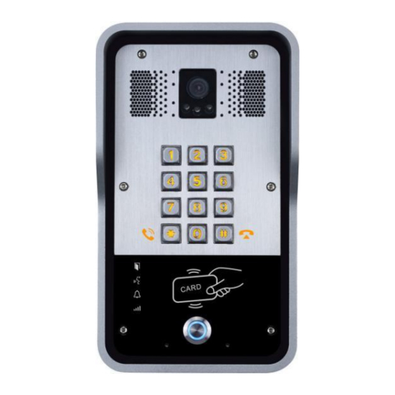
IP3667 Package Contents Connectors Door Phone Quick Installation Mounting Template Guide Screw and RFID Cards Wrench Physical Specifications Device size 223 x 130 x 74mm Weight 1800g Front Panel Infrared light Speaker Camera Photoresistor Numeric keypad (password and dialing) Lock status... - Page 4 IP3667 Interface Description Camera Get the video. Infrared light & To Compensate for lack of ambient light Photoresistor The door phone has a built-in speaker for convenient communication Speaker and alert use. The door phone has a built-in microphone hidden in the pinhole located on the front panel.
- Page 5 IP3667 Network Connector Power and Electric-lock Connector +DC12V S-IN S-OUT 12V DC Input Electric-lock switch Indoor switch JP1 Jumper There are two power supply modes for electric-lock as shown in the picture below. (The default is “Passive Mode:”). Passive Mode: When the electric-lock starting current is more than 12V/650mA, you must use the external drive mode, the electric lock interface for short circuit output control.
- Page 6 IP3667 Wiring instructions NO: Normally Open Contact; COM: Common Contact; NC: Normally Close Contact Driving Mode Electric-lock Mode Connections No electricity Electrify Jumper Active Passive when open when open √ √ √ √ √ √ √ √ √ √...
-
Page 7: Installation
3. Installation Front Panel Main Part of Intercom Rain Shade Back Panel Figure 1 Three Major Parts of IP3667 Step 1: Installation preparation A. Check the following contents: Hex wrench x 1 RJ45 plugs x 2 (1 spare) ... - Page 8 IP3667 Step 3: Removing hanging shell A. With L-shaped screwdriver, unpack the front panel according to diagram (3) (Counter-clockwise) and (4) Figure 3 Figure 4 B. With Phillips screwdriver, unpack the rain shade and the main part of intercom according to diagram (5)
- Page 9 IP3667 B. With 4 TA5*40mm screws, tighten the back panel on the wall according to diagram (6). C. Connect the cables of RJ45, power, and electric-lock to the motherboard socket as mentioned in connectors description (refer to Section 2). D. Test whether there is electricity by doing the following: Press the # button for 3 seconds to get the IP address of intercom by voice.
-
Page 10: Searching Door Phone
Note: It is strongly encouraged to assign either a static or reserved DHCP IP address to the IP3667, as well as any desk phones that will receive IP calls from the IP3667 or access its video feed. Otherwise the IP... -
Page 11: Sip Door Access Control Setting
IP3667 5. IP Door Phone Setting Step 1: Log into the door phone Input IP address (e.g. http://192.168.1.149) into address bar of PC’s web browser. The default user name and password are both admin. Step 2: Add the SIP account. -
Page 12: Door Unlocking Setting
IP3667 Step 4: Door Phone Setting 6. Door Unlocking Setting Local 1) Local Password Step 1: Go to EGS Setting → Features → Set Local Password (The default is “6789”). Step 2: Use the device’s Numeric Keyboard to input password and “#” key, and then the door will be... - Page 13 IP3667 2) Private Access Code Step 1: Go to EGS Access → Access Rule → set Access Code. Step 2: Use the device’s Numeric Keyboard to input password and “#” key, and then the door will be unlocked. Remote Remote Password Step 1: Go to EGS Setting →...
Need help?
Do you have a question about the IP3667 and is the answer not in the manual?
Questions and answers