Table of Contents
Advertisement
Quick Links
Advertisement
Table of Contents

Related Manuals for Altana BYK wave-scan 3 ROBOTIC

Summary of Contents for Altana BYK wave-scan 3 ROBOTIC
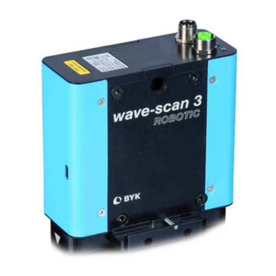
- Page 1 Measure what you see wave-scan 3 ROBOTIC Operating Instructions...
- Page 2 BYK-Gardner GmbH © Copyright 2020 BYK-Gardner GmbH All rights reserved 301 200 141 E 2010 wave-scan 3 ROBOTIC...
-
Page 3: Table Of Contents
BYK-Gardner GmbH Table of Contents Table of Contents 1 Introduction ..........................1.1 Safety Instructions ..........................1.2 Declaration of Conformity........................1.3 Handling Instructions .......................... 1.4 Prerequisites ............................2 Hardware............................2.1 Delivery Content..........................2.2 Mounting Board ..........................10 2.3 Power Supply ............................11 2.4 Status LEDs............................ - Page 4 1 | Introduction BYK-Gardner GmbH wave-scan 3 ROBOTIC 301 200 141 E 2010...
-
Page 5: Introduction
BYK-Gardner GmbH Introduction | 1 1 Introduction This instruction manual is an important part of this instrument. It contains essential information about setting up, placing in service and use. If you pass the device on to another user, please ensure that the instruction man- ual is included with the instrument. -
Page 6: Safety Instructions
1 | Introduction BYK-Gardner GmbH 1.1 Safety Instructions No claims of product liability or warranty can be honored if the device is not operated in accordance with the operating instructions and the instruc- tions on the instrument. The measurement unit is a class 1 laser product. The label shown below is on the base of the measurement unit. - Page 7 BYK-Gardner GmbH Introduction | 1 Only devices that meet the requirements for low-voltage safety may be connected to the control interface (green). For operation with the external power supply, care should be taken to en- sure the nominal voltage of the power supply unit (see the manufacturer’s plate on the power supply unit) matches the voltage supplied by the power outlet.
-
Page 8: Declaration Of Conformity
1 | Introduction BYK-Gardner GmbH 1.2 Declaration of Conformity BYK-Gardner GmbH Lausitzer Strasse 8 D-82538 Geretsried declare, that this instrument complies with the requirements of the follow- ing EU directives: • 2014/30/EU - Electromagnetic Compatibility • 2014/35/EU - Low Voltage The following harmonized standards were applied: •... -
Page 9: Hardware
BYK-Gardner GmbH Hardware | 2 2 Hardware Before operating the instrument for the first time, please read the Operat- ing Instructions and take particular notice of the Safety Instructions. Unpack the instrument and check the delivery for completeness. 2.1 Delivery Content The system comes complete with: Measurement unit, cover, test tile, certifi- cate and safety instructions. -
Page 10: Mounting Board
2 | Hardware BYK-Gardner GmbH 2.2 Mounting Board A mounting board is required to mount the instrument to the robot arm. This board is not part of the delivery. A drawing, that contains all dimen- sions for the production of the mounting board, is enclosed with each in- strument. -
Page 11: Power Supply
BYK-Gardner GmbH Hardware | 2 During the measurement, a distance of 15 mm ± 2 mm to the surface is to be kept. The angle-deviation of the perpendiculars on the surface can amount to at most 2° to all sides. NOTICE The mounting can be done on the left or on the right side of the measure- ment unit. -
Page 12: Status Leds
2 | Hardware BYK-Gardner GmbH 2.4 Status LEDs The instruments has four Light Emitting Diodes (LEDs) for status indication. Illustration 5: Status LEDs of wave-scan 3 ROBOTIC 1 Lights in green whenever the device detects a valid link. Blinks in green when CRS is active (high) indicating activity. 2 Lights in blue when the operating speed is 100 Mbps. -
Page 13: Cabling
BYK-Gardner GmbH Cabling | 3 3 Cabling The delivery comprises the cables required for initialization and to connect instrument on robot arm with PC: • Power Cables [} 14] • Data Cables [} 16] • USB Cable [} 18] WARNING To avoid instrument damage, only use the cables which are part of the de- livery for connecting the instruments! 3.1 Application Example Following picture gives an example how the cables can be placed in a robot... -
Page 14: Power Cables
3 | Cabling BYK-Gardner GmbH 3.2 Power Cables The power interface is a black 8-pole plug. The power supply input is 24 V ; max. 0.75 A. Illustration 7: Polarity diagram for pins M12, 8-pin, A-coded, view pen side Pin ROBOTIC Cable Color Cable Color Power... - Page 15 BYK-Gardner GmbH Cabling | 3 301 200 145 301 200 144 301 200 143 8 m for robot - torsion capable 20 m on flor - oil resistant 10 m for track chain Lappkabel 0028900 4-wire Lappkabel 0028900 4-wire Lappkabel 0029657 4-wire Binder Binder Binder...
-
Page 16: Data Cables
3 | Cabling BYK-Gardner GmbH 3.3 Data Cables For data communication a proprietary LAN cable is used. The communica- tion interface is a green 4-pole plug. Illustration 10: Pin assignment M12, 4-pin, D-coded, view socket side No. ROBOTIC Data Cable Color 4-pin M12-D 8-pin RJ-45 1 TX+... - Page 17 BYK-Gardner GmbH Cabling | 3 301 200 149 301 200 148 301 200 147 8 m for robot - torsion capable 20 m on flor - oil resistant 10 m for track chain Lappkabel 2170894 4-wire Lappkabel 2170894 4-wire Lappkabel 2170888 4-wire Lappkabel Phoenix Phoenix...
-
Page 18: Usb Cable
3 | Cabling BYK-Gardner GmbH 3.4 USB Cable For initialization the instrument provides an additional USB port. Illustration 13: Interfaces on wave-scan 3 ROBOTIC 1 Power interface (black) 2 Data interface (green) 3 USB type C interface Perform following steps: 1. Connect the instrument via the USB cable in the delivery with your PC. 2. -
Page 19: Operation
BYK-Gardner GmbH Operation | 4 4 Operation The wave-scan 3 ROBOTIC is configured and operated completely via the software smart-robotic, which is installed along with smart-chart: Software Installation [} 19] Firmware Update [} 19] Device Configuration [} 20] Productive System [} 24] The complete configuration usually takes place in a test environment. After successful test the configuration is transferred to the productive system. -
Page 20: Device Configuration
4 | Operation BYK-Gardner GmbH Illustration 14: Firmware update for wave-scan 3 ROBOTIC Click the Start Update button. When the update has finished, close the program. 4.3 Device Configuration Before the wave-scan 3 ROBOTIC can be put into operation, following steps have to be performed: Driver Installation [} 20] Device Connection... - Page 21 BYK-Gardner GmbH Operation | 4 After driver installation the USB cable is to be connected to activate the de- vice detection in Windows. Illustration 16: Cabling for USB driver installation 1 Instrument 2 USB port on instrument wave-scan 3 ROBOTIC 3 USB port on PC For the installation of the device in the Windows system the USB connec- tion is sufficient.
-
Page 22: Device Connection
4 | Operation BYK-Gardner GmbH 4.3.2 Device Connection To access the device via smart-robotic, the instrument has be connected to the power supply too. Illustration 18: Cabling for connection test 1 Instrument 2 USB port on instrument wave-scan 3 ROBOTIC 3 USB port on PC With power supply and USB connection the instrument can now be ac- cessed in smart-robotic in the Devices >... -
Page 23: Device Test
BYK-Gardner GmbH Operation | 4 4.3.3 Device Test With USB connection and power supply the device can be tested. During the test a measurement is performed. The wave-scan ROBOTIC performs a non-contact measurement. A possible test setup is shown below. Illustration 20: Setup for device test 1 Sample to be measured 2 Measurement distance 15 mm... -
Page 24: Productive System
4 | Operation BYK-Gardner GmbH 4.4 Productive System The instrument is designed to measure in full automatic mode. Only re- quirement is to configure the instrument(s) and the data output inter- face(s) in smart-robotic. After are successful testing the configuration can be copied from the test system to the productive system and adapted. -
Page 25: Checking
BYK-Gardner GmbH Checking | 5 5 Checking Due to the underlying measurement principle, no calibration of the instru- ment is required. 5.1 Principle It is recommended, however, to check the functionality of the instrument at regular intervals (about once every 3 months). Illustration 24: Instrument and checking tile The reference tile included with delivery is provided for this purpose. -
Page 26: Procedure
5 | Checking BYK-Gardner GmbH 5.3 Procedure Perform a measurement with the robot. The values for a correct reading are printed in the retraceable certificate and on the reference tile. These values can be entered in smart-robotic for a pass / fail check. Illustration 26: Daily check in smart-robotic If the value measured on the reference tile is within the printed tolerance range, the requirements are met. -
Page 27: Appendix
BYK-Gardner GmbH Appendix | 6 6 Appendix 6.1 Cleaning and Maintenance 6.1.1 Cleaning the Test Tile Since the surface of the test tile is highly sensitive, cleaning must be under- taken with great care. To clean standards, use a new lint-free cloth, dust-free lens paper or an op- tical cloth as included with the device. -
Page 28: Delivery Notes
6 | Appendix BYK-Gardner GmbH 6.2 Delivery Notes 6.2.1 Product Highlights • State-of-the-art chip technology with high speed computing power – needed for calculation of scales using e.g. Fast Fourier Transformation • New LAN interface - today´s industry standard • New, flexible detachable mount - compatible to predecessor •... -
Page 29: Download Links
BYK-Gardner GmbH Appendix | 6 6.2.4 Download Links 6.2.4.1 Instrument Software • Smart-process (including smart-robotic and device driver) • Operating Instructions (smart-robotic): 300 003 099 - 2010 https://www.byk-instruments.com/software#wave-scan 6.2.4.2 Instrument Documentation • Safety Instructions: 301 200 080 - 2004 • Operating Instructions: 301 200 141 - 2010 https://www.byk-instruments.com/p/7410 6.2.5 Accessories List https://www.byk-instruments.com/c/smart-process/p/4831... -
Page 30: Error Messages
6 | Appendix BYK-Gardner GmbH 6.3 Error Messages ID Message Text Acquired measurement data is not valid Measurement timeout Device temperature too high Device temperature too low Initialization error Component not initialized 1001 Camera capture timeout 1002 Camera initialization timeout 1401 IR laser error detected 1405... -
Page 31: Technical Data
BYK-Gardner GmbH Appendix | 6 6.5 Technical Data 6.5.1 Measuring Data Light source Laser Diode LED and IR-SLD Laser diode Laser Class 1, P ≤ 390 µW, λ=670 nm, DIN EN 60825-1:2015-07 Measure range Dullness: 1 to 40 LW, SW: 0 to 100 Wa –... - Page 32 Download your software from: https://www.byk-instruments.com/software Download your manual from: https://www.byk-instruments.com/manuals Find more information on our products and services: https://www.byk-instruments.com 301 200 141 E 2010...
Need help?
Do you have a question about the BYK wave-scan 3 ROBOTIC and is the answer not in the manual?
Questions and answers