
Subscribe to Our Youtube Channel
Related Manuals for EZAutomation EZ7-TouchPLC

Summary of Contents for EZAutomation EZ7-TouchPLC
- Page 1 EZ7-TouchPLC Micro Quick Start Guide Doc Version 1.0, 08/2019 EZAutomation.net 1-877-774-EASY (3279)
-
Page 2: Table Of Contents
Using EZTouch Editor Serially Connected to EZ7: ......................36 9.1.2 Using IP Configuration Utility: ............................. 38 ................................39 ETTING MAINTENANCE AND TROUBLESHOOTING ........................40 .................................... 40 ENERAL ..............................40 ISPLAY ERIFICATION ESTS ................................41 PDATE IRMWARE ................................43 ROUBLESHOOTING Page 2 of 44 EZ7-TouchPLC Micro... - Page 3 Warnings Programmable control devices such as the EZ7-TouchPLC Micro units are not fail-safe devices and such as must not be used for stand-alone protection in any application. Unless proper safeguards are used, unwanted start-ups could result in equipment damage or personal injury. The operator must be made aware of this hazard and appropriate precautions must be taken.
-
Page 4: Product Overview
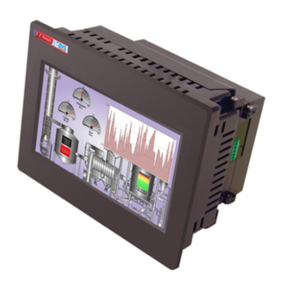
Thank You for your interest in AVG Automation’s latest unique offering, the EZ7 Series TouchPLC. EZ7-TouchPLC is two piece products: Front part consisting of display (and touch screen) housed in metal, and a back part that has PLC processor. Front part is installed on the front of the control cabinet, while the back part is installed on the back of the control cabinet door. -
Page 5: Part Number
EZ7DT-T7C-FR EZ7 7” Inch Display Only EZ7DT-T8C-FR EZ7 8” Inch Display Only EZ7DT-T10C-FR EZ7 10” Inch Display Only EZ7DT-T12C-FR EZ7 12” Inch Display Only Cable EZ7DT-CBL-012 Cable between Front and back of EZ7, 12” Page 5 of 44 EZ7-TouchPLC Micro... -
Page 6: Specification
13.584”x10.594”x 4.299” 13.00”x16.75”x6.25” External Dimensions (204.41 x 156.11 x 109.87mm) (276.71 x 222.20 x 110.82mm) (34 5x 269.1 x 109.20mm) (330.2 x 425.25 x 158.7mm) 2 lbs 3.5 lbs 4.5 lbs 7 lbs Weight Page 6 of 44 EZ7-TouchPLC Micro... -
Page 7: Quick-Start
Serial or Ethernet or USB Connection Pre-requisite- Make sure you have everything you need: This is what you will need to get started: EZ7-TouchPLC Unit A PC Running Windows 7 or Windows 10 with EZTouch Editor Programming Software* installed ... -
Page 8: Installation
Enhancement of a system’s noise level immunity and its tolerance to other environmental hazards can be accomplished by following proper system installation guidelines. The recommendations are of a general nature and constitute good industrial installation practice. Page 8 of 44 EZ7-TouchPLC Micro... - Page 9 Earth. This not only provides for safe operation, it will also drain out any conducted RFI to Earth, away from the CPU's signal ground. Page 9 of 44 EZ7-TouchPLC Micro...
- Page 10 Primary power leads to the control equipment (Base power terminals) should be made with a two wire twisted cable with approximately 12 turns per foot. The length of these cables should be kept to a minimum, and to the greatest extent possible, such cable runs should be kept separate from other wiring. Page 10 of 44 EZ7-TouchPLC Micro...
-
Page 11: Mounting Information
6.09[154.8] 5.91[150] 3.43[87.1] 7.42[188.3] 4.81[122.2] 0.78[19.9] 5.52[140.2] 8” 10.61[269.6] 6.41[162.8] 8.52[216.4] 4.81[122.3] 9.89[251.3] 4.81[[122.3] 0.78[19.9] 5.52[140.2] 10” 12.00[304.8] 8.37[212.6] 9.50[241.3] 6.25[158.6] 9.89[251.2] 4.81[122.3] 0.78[19.9] 5.52[140.2] 12” 13.19[335] 9.80[249] 10.63[270] 7.38[187.5] 9.89[251.3] 4.81[122.3] 0.97[24.7] 5.52[140.2] Page 11 of 44 EZ7-TouchPLC Micro... -
Page 12: T7C (7" Display) Mounting Dimensions
5.2.2 T7C (7” Display) Mounting dimensions 5.2.3 T8C (8” Display) Mounting dimensions Page 12 of 44 EZ7-TouchPLC Micro... -
Page 13: T10C (10" Display) Mounting Dimensions
5.2.4 T10C (10” Display) Mounting dimensions 5.2.5 T12C (12” Display) Mounting dimensions Page 13 of 44 EZ7-TouchPLC Micro... -
Page 14: Mounting Instructions
These steps are described below with pictures: The EZ7-TouchPLC is stud mounted. All the necessary mounting hardware is provided with the unit. Both the processor and the TOUCHPLC screen have studs with nuts provided. Below is a full installation guide with step by step instructions. - Page 15 3. Then use the provided screws (6-32 Philips Flat head ½” length. (X 4),Screw driver – Philips #2 ) to install the Processor Box to the inside of the Control Cabinet. Also make sure that the HDMI cable is pulled through the large middle hole. Page 15 of 44 EZ7-TouchPLC Micro...
- Page 16 5. Now insert all studs through their respective holes, and use provided nuts (Hex-head nut, size 10-32 requiring 3/8” nut driver/wrench) to secure the front to the cabinet. 6. When looking from bottom or top the screen should look like the image below. Page 16 of 44 EZ7-TouchPLC Micro...
-
Page 17: Wiring
Blinking Red / Continuously Red Some Panel Issue has occurred. Please try a power cycle, if that does not fix the issue please contact Tech Support. No Light Power source not connected or inadequate Page 17 of 44 EZ7-TouchPLC Micro... -
Page 18: Micro Plc - I/O
AWG wires, or FOUR 22 AWG wires in every terminal. You will need a 2.5mm blade screwdriver (P/N EZIO-SCDRV) to work with the I/O terminals and wiring Wires Supported UL rated at 300 volts, 10 amps 14 AWG Page 18 of 44 EZ7-TouchPLC Micro... -
Page 19: Terminal Layout
6.2.2 Terminal Layout Please note: On 44 I/O unit, Only 2 analog In (Pin 6, 8 of terminal block TBA) and 2 analog out (Pin 1, 3 of TBA) available. Page 19 of 44 EZ7-TouchPLC Micro... -
Page 20: Terminal Pinouts
6.2.3 Terminal Pinouts Page 20 of 44 EZ7-TouchPLC Micro... - Page 21 Page 21 of 44 EZ7-TouchPLC Micro...
-
Page 22: Digital I/O Specifications
ON to OFF Response 2- 4 ms. Typical 3 ms Status Indicators Red LED for each input Commons 2 points Fuse No Fuse 1 of 14 AWG, 2 of 18 AWG Wires 4 of 22 AWG Page 22 of 44 EZ7-TouchPLC Micro... - Page 23 1 Amp per module, turns off outputs Short Circuit Protection upon short-circuit detection Base power required (3.3V) 40mA, all outputs on 1 of 14 AWG, 2 of 18 AWG Wires 4 of 22 AWG Page 23 of 44 EZ7-TouchPLC Micro...
- Page 24 5000VAC at 50/60Hz for one minute between Coil & Contacts Dielectric Strength 1000VAC at 50/60Hz for one minute between Contacts Operate Time Max 10ms Release Time Max 5ms Status Indicators Red LEDs Relay Output Wiring Page 24 of 44 EZ7-TouchPLC Micro...
-
Page 25: Analog I/O Specifications
6.2.5 Analog I/O Specifications Page 25 of 44 EZ7-TouchPLC Micro... - Page 26 Page 26 of 44 EZ7-TouchPLC Micro...
-
Page 27: Programming
The CPU reads the status of all inputs, and stores them in an image table. Image Table is EZ7-TouchPLC Micro internal storage location where it stores all the values of inputs/outputs for ONE scan while it is executing ladder logic. The CPU uses this image table data when it solves the application logic program. -
Page 28: Create A Project
Click on Open/New Project Press ENTER. You may get a confirmation message Select Project Name and folder location using Browse button. Select EZModel: Panel Family – in this case EZ7-TouchPLC Modular, Micro, Micro and Nano Select size (Only radio buttons corresponding to available sizes are enabled) - Page 29 Once again, a dialog box will appear. Enter "O1” as the address string. Click OK. Click on Instructions > Line to wire “NO Contact” and “NO Coil.” Your screen should look like this when finished: Page 29 of 44 EZ7-TouchPLC Micro...
- Page 30 3. Click anywhere on the screen to place the Button object. Double click the icon to open its object dialog box if you need to adjust the object's appearance or attributes. Clicking "Simulates Press" will allow you to toggle between on and off states. Page 30 of 44 EZ7-TouchPLC Micro...
-
Page 31: Transfer Project
RS-232 port on the PC, a USB to RS-232 converter may be used to connect the programming cable to the PC. 2. Select in the drop down (that appears next to Serial radio button after the option is chosen) COM port on Page 31 of 44 EZ7-TouchPLC Micro... - Page 32 3. After confirming the mode to transfer the project, click Start to write the project data from the PC to the EZ7 Series TouchPLC. When finished, a Transfer Completed message will be displayed. Click OK to continue and the project is now transferred. Page 32 of 44 EZ7-TouchPLC Micro...
-
Page 33: Cpu Memory
SD- System Discretes 1-64 READ_WRITE DISCRETE SD10 XR- Index Registers READ_WRITE WORD XR10 NONE #R – Value Registers #R1 - #R4 READ_WRITE WORD Note: Does not Support Access to a Bit of Word (E.g.: R100/ 0, R100/5…etc) Page 33 of 44 EZ7-TouchPLC Micro... -
Page 34: Mapping Conventions
Discrete Inputs are denoted using an “I” pre-fix (e.g. I1, I4, etc.). The maximum number of physical Inputs available in an EZ7-TouchPLC Micro is 24. Hence, you may only use I1 – I24 in your main logic. Note: All the discrete type EZ7 Inputs are mapped to Discrete Input bits. In the example above, the output bit O1 will be turned on when input I1 allows power through the rung. - Page 35 The Index Register data type is represented by an “XR” prefix (e.g. XR1, XR2 etc.). There are 4 XR memory locations available in EZ7-TouchPLC Micro. “XR” is a Read- Write data type and it is mainly used to point to the correct address of “R”...
-
Page 36: Setting Ip Address And Date/Time
The EZ7-TouchPLC Micro will arrive with a factory-programmed IP Address that may need edited to be compatible with your LAN network. Once the IP Address has been adjusted to the LAN, the EZ7-TouchPLC Micro can receive programming instructions through either the serial port (COM1) connection or via the Ethernet. Follow the steps below to use the editing software to update the IP Address information though a COM port on the EZ7-TouchPLC Micro. - Page 37 Click Set-up > Ethernet Set up. A dialog box will appear displaying the current IP parameters. Once the dialog box appears, select 'Configure Ethernet Attributes.' Type in the necessary changes and click 'Set Ethernet Parameters.' Click OK. Next, save the project. Page 37 of 44 EZ7-TouchPLC Micro...
-
Page 38: Using Ip Configuration Utility
AVG devices connected to the local area network (LAN) even if a device’s IP address is not on the same subnet. To download this free utility please visit our website at www.ezautomation.net and click on the downloads tab. 1. Install the IP Config Utility. -
Page 39: Setting Date/Time
Press 1 then Mon. c. Press 1 then 3, followed by Yr. 4) Once finished, press Exit to return to the previous screen. Pressing Exit again will bring you back to the main screen. Page 39 of 44 EZ7-TouchPLC Micro... -
Page 40: Maintenance And Troubleshooting
2. A new screen will appear. Press each box individually to ensure that the touchscreen is properly responding. 3. Once finished, press Exit to return to the previous screen. Pressing Exit again will bring you back to the main screen. Page 40 of 44 EZ7-TouchPLC Micro... -
Page 41: Update Firmware
2. The upper left corner will then display the firmware currently enabled on the unit. To update firmware: There are several methods to update the firmware for an EZ7-TouchPLC Micro unit. Previously, it was explained how to update firmware through an OEM Packager file. Alternatively, the user can follow the steps below to update firmware through the EZ Series Software and a COM port on the EZ7-TouchPLC Micro unit. - Page 42 5. After the project loads, click Setup > Upgrade Firmware. A dialog box will appear requesting the firmware file you would like to load to the unit. 6. Use Browse to locate the appropriate firmware version. Page 42 of 44 EZ7-TouchPLC Micro...
-
Page 43: Troubleshooting
If you encounter difficulties while using our EZ7 Series TouchPLC device, please consult the table below. Additional assistance is also available within the Panel Editor Programming Software Help. Alternatively, you may also find answers to your questions on our website www.ezautomation.net. Problem... - Page 44 Out of Warranty Services If your EZ7-TouchPLC Micro is out of warranty, contact EZ Automation at 1-877-774-EASY for an evaluation of repair costs. You can then decide whether it is more economical to proceed with the repairs or to upgrade your system with a new unit.
Need help?
Do you have a question about the EZ7-TouchPLC and is the answer not in the manual?
Questions and answers