Table of Contents
Advertisement
Quick Links
Goblin – Operational Manual
U
M
SER'S
ANUAL
G
OBLIN
Electrical Load Manager/Demand Controller
This document contains the latest technical information about Goblin which is
a micro-controller based Electrical Load Management/Demand controller. The
unit is tested against latest "MTE" Standard Model PRS400.3 having basic
accuracy of 0.02%, traceable upto International Standards derived using
appropriate ratio techniques.
The product, Goblin is sophisticated electronic equipment, and the user is
advised to read this User's Manual carefully before attempting to install or
operate the equipment.
Published on:------
Document Version: 1.1
TRINITY
[1]
Advertisement
Table of Contents

Related Manuals for Trinity Goblin


Summary of Contents for Trinity Goblin
- Page 1 ANUAL OBLIN Electrical Load Manager/Demand Controller This document contains the latest technical information about Goblin which is a micro-controller based Electrical Load Management/Demand controller. The unit is tested against latest "MTE" Standard Model PRS400.3 having basic accuracy of 0.02%, traceable upto International Standards derived using appropriate ratio techniques.
- Page 2 Trinity Dealer or Factory. You are responsible for all costs (shipping, insurance, travel time) in getting the product to the service location.
-
Page 3: Table Of Contents
Programming Mode Using Utility ................34 Control Outputs ......................36 Alarm Action ......................36 Goblin as a Load Manager / Demand Management ..........37 Appendix ........................38 Address Map of Various Parameters for 3P4W installation ........38 ... -
Page 4: Introduction
Goblin – Operational Manual Introduction The digital power meter GOBLIN is a micro-controller based unit which not only measures a host of electrical parameters to display them on a 128 X 64 graphical backlit LCD, but also acts as a comprehensive load managing device due to its four numbers of output relay contacts. -
Page 5: Technical Specifications
Goblin – Operational Manual Technical Specifications Parameters Type Name Statistics Three Phases and Neutral of a 3P4W system / Three Phases of a 3P3W system Direct Voltage Input : Up to 500V L-L, Up to 300V L-N Voltage PT Ratio... - Page 6 Goblin – Operational Manual MISCELLANEOUS Parameters Type Name Statistics Bezel 144 X 144 mm Panel Cutout 138 X 138 mm Depth of installation 55 mm Display 128 X 64 graphical Backlit LCD Operating temp 10°C to 50°C Weight 0.65 Kgs (Approx.) Operating Current 0.4% to 120% of CT primary...
-
Page 7: Installation And Commissioning
Goblin – Operational Manual Installation and Commissioning The Goblin supports two installation modes – 3P4W and 3P3W. The installation process of these modes is described below: 3P4W Mode Installation Follow these steps to install / commission the unit. 1. Push the unit into the panel and mount using the clamps provided. Connect the Auxiliary supply to the terminals marked P and N. - Page 8 Goblin – Operational Manual 7. Now, the unit needs to be programmed for the various parameters which are field programmable. For this refer to next section “OPERATIONAL DETAILS” 8. The unit is ready for operation. TRINITY...
-
Page 9: 3P3W Mode Installation
Goblin – Operational Manual 3P3W Mode Installation Follow these steps to install / commission the unit. 1. Push the unit into the panel and mount using the clamps provided. Connect the Auxiliary supply to the terminals marked P and N. The Auxiliary supply range is 80 VAC to 270 VAC. -
Page 10: Connection Scheme
Goblin – Operational Manual Connection Scheme TRINITY [10]... -
Page 11: Rs485 Connection
Goblin – Operational Manual RS485 Connection TRINITY [11]... -
Page 12: Operational Details
Goblin – Operational Manual Operational Details The load manager, GOBLIN is a versatile meter, with all the features needed to implement with a robust electrical load management system. It can be configured to suit most control and communication needs. This is achieved by making as many parameters field programmable, as much possible. -
Page 13: Programming Mode
Goblin – Operational Manual Programming Mode The unit is designed with a secure default password,”1947”. The password is also changeable from 0 to 9 according to user’s desire (see in the next section, programmable parameter, “Changing a Password”). To enter into Programming... -
Page 14: Setting Neutral Ct Primary, Neutral Ct Secondary, Password And Log Duration
For logging the parameters, the Log Duration (LOG DUR) can be specified from 1 to 60 minutes. GOBLIN has the capability to log data on its own Non-volatile RAM. This data is logged in an FIFO buffer. Once the buffer (19691 records) is full, the oldest data is discarded and the newest data is filled into the buffer. -
Page 15: Setting Real Date, Time, Baud Rate And Unit Address For Rs485 Port
ALARM VAL:1 R_HYSTER.:1 Relay (rly) GOBLIN has four relay contacts, which are individually field programmable from 1 to Alarm on There are seven alarm parameters: Avg. Volts [(Vry+Vyb+Vbr)/3], Avg. Amps [(Ir+Iy+Ib)/3], KVA, KW, KVAR, KW Demand, KVA Demand and PF. These... -
Page 16: Selecting Events, Event Parameters, Event Values And Hysteresis
Goblin – Operational Manual parameters are programmable for each alarm relay according to user’s requirement. In case, user is not desired for alarm, the Alarm should be set to NONE. Alarm Value Alarm values are freely programmable from 1 to 10000. In case of Avg. Volts, the parameter is freely programmable from 1 to 70000. -
Page 17: Selecting Demand Window (Both Kw And Kva), Installation Type And Reset Demand
Goblin – Operational Manual which the event will log. E.g. If the EVENT ON for EVENT 1 has been selected to KW, and the value is set to 450, the EVENT 1 will log when the KW exceeds 450 and remains so for 1 minute. -
Page 18: Resetting Energy, Min-Max Parameters, Logs And Max Demand
Goblin – Operational Manual Resetting Energy, Min-Max parameters, Logs and Max Demand In the above Programming Mode, press key till the unit enters into the following display and then, set such as steps before. >RESET ENERG:NO RST MIN-MAX:NO RESET LOGS:NO... -
Page 19: Run Mode
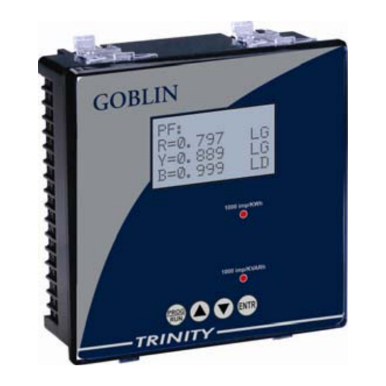
Goblin – Operational Manual Run Mode In the run mode, the various parameters measured/calculated by the meter are displayed on different pages on a 128X64 graphical Backlit LC Display. Run Mode display in 3P4W and 3P3W Vry=408.5 Vyb=413.1 Vbr=415.7 Frq.=49.80 The first page shows phase to phase voltage of three phases (i.e., Vry, Vyb and... - Page 20 Goblin – Operational Manual R=0.797 Y=0.784 B=0.813 The fourth page shows PF in three phases (i.e., R-phase, Y-phase and B-phase) in second line, third line and fourth line respectively. KW=17.27 KVA=21.61 KVAR=13.07 PF=0.796 The fifth page shows Active Power (KW), Apparent Power (KVA) and Reactive power (KVAR) in first line, second line and third line respectively.
- Page 21 Goblin – Operational Manual KW DM=456 KW MD=751 Dt=02/11/00 Tm=21:19:25 The eighth page shows the KW present Demand (DM) along with the Maximum Demand (MD) reached. There are a few points regarding Demand and maximum demand display, which need to be noted.
- Page 22 Goblin – Operational Manual If the demand is calculated by the meter, based on sliding window technique, then unlike utility installed demand meters, this demand figure does not reset to zero at the end of the 15 minutes or 30 minutes integration window.
- Page 23 Goblin – Operational Manual the Harmonic data page for that current will show 0.0 % for all values. The Harmonic data is also available over the serial communication link, RS 485, Modbus protocol. In case of 3P3W installations, the Harmonic data of Y phase is not applicable.
- Page 24 Goblin – Operational Manual The twenty-fifth page shows date and time of data logging for all parameters. The maximum LOGS is upto 19691. Once the LOGS is overflow, LOGS will start from 1 and OVERFLOW will show YES. This Log can be seen after downloading the data by using USB data or pen drive.
-
Page 25: Communication
USB 2.0 and pen drive for downloading of logged data are also available in Goblin. These options make it possible for a user to select Goblin to provide power and energy information into a variety of existing or new control systems. Each communication option supports data transfer with external devices or applications. -
Page 26: Installing The Usb Software
Goblin supports USB 2.0 and Pen Drive for downloading of logged data. For USB, users are provided a CD for USB utility installation along with the purchase of Goblin. Before installing the software, users are advised to read carefully Read Me document in Logger disc for a list of minimum system requirements to be installed, if uninstalled before. -
Page 27: Installation Of Usb Driver
Goblin – Operational Manual and Just me of which Everyone is selected by default. 4. To confirm the installation, click Next in the next wizard and wait for some time while proceeding the installation. After completing the installation, the wizard will display the Logger Setup has been installed successfully. - Page 28 Goblin – Operational Manual The wizard will ask if your hardware comes with an installation CD or floppy disk, insert it now. Select the wizard option, Installation from a list or specific location and click Next to give the following dialog box where the file is located.
-
Page 29: Handling The Logger Window
Goblin – Operational Manual location and click check box of Include this location in the search to specify path of usb drivers and then, click Next to get the path where the file is located. 5. Now click OK, to complete the wizard. -
Page 30: Exporting The Logged Data Including Min/Max Events And Harmonics Data
Goblin – Operational Manual 2. In the unit type list, select the Goblin and click OK and to start downloading, click DOWNLOAD and then, the logged data will open with the following logger window. 3. In this LOG DATA page, click HARMONICS DATA at the bottom of the window to open the harmonics data for all current and voltage. -
Page 31: Graph Representation
Goblin – Operational Manual Graph Representation The graph plots for various selected parameters of Logged data including harmonics distortion along with date and time. Hence, the back ground color, Axis colors and Label colors can also be selectable. Plotting a Graph for Logged data. - Page 32 Goblin – Operational Manual 4. If the parameters selected are not desired, double-click again in the check box to remove the selected parameter from the list. 5. To change the color of the selected parameters displayed at right side list (e.g.
-
Page 33: Data Download Using A Pen Drive
Goblin – Operational Manual 8. The plotted graphs can be saved and printed clicking respectively. Hence, to return into previous Logger Windows, click Data Download Using a Pen Drive. The unit supports pen drive for downloading logged data. The data exported as before into an excel sheet using a USB 2.0 can also be downloaded using a pen... -
Page 34: Programming Mode Using Utility
Logger Utility. Using utility, user can easily specify for all the programmable parameters which is also more convenient than the programming in unit. Make sure USB cable coming from the PC is connected to Goblin where the USB port is provided at the top of the unit. - Page 35 Goblin – Operational Manual Select Goblin(Prog) in list box and click OK that will open the page such as shown below. By default the cursor will blink in password box which shows user will enter password and enter the password used in meter and then, click to enter into Programming Mode.
-
Page 36: Control Outputs
Goblin – Operational Manual Control Outputs The relay contacts provided in GOBLIN are rated for 3A @ 230VAC. They are also protected by snubbers against fast voltage transients which occur when inductive loads are switched off. Thus, the following points are to be taken care of when using these relay contacts: 1. -
Page 37: Goblin As A Load Manager / Demand Management
Voltage exceeds certain value, second when the Avg. Amps exceeds some level, third for KW, or KVAR or PF or Demand and so on. This allows the user to deploy GOBLIN as a true LOAD manager, to generate alarm / trip signals for four different conditions! -
Page 38: Appendix
Goblin – Operational Manual Appendix Address Map of Various Parameters for 3P4W installation Modbus Parameters Format Address 40200 Vln-R U-Long 40202 Vln-Y U-Long 40204 Vln-B U-Long 40206 Vln-Avg. U-Long 40208 Vll-RY U-Long 40210 Vll-YB U-Long 40212 Vll-BR U-Long 40214 Vll- Avg. - Page 39 Goblin – Operational Manual 40288 5th Hvr U-Long 40290 7th Hvr U-Long 40292 8th Hvr U-Long 40294 9th Hvr U-Long 40296 11th Hvr U-Long 40298 15th Hvr U-Long 40300 THD Hvr U-Long 40302 3rd HIr U-Long 40304 5th HIr U-Long...
-
Page 40: Address Map Of Various Parameters For 3P3W Installation
Goblin – Operational Manual Address Map of Various Parameters for 3P3W installation Modbus Parameters Format Address 40200 U-Long 40202 40204 U-Long 40206 40208 40210 40212 40214 Vll- Avg. U-Long 40216 U-Long 40218 U-Long 40220 U-Long 40222 Iavg. U-Long 40224 I neutral... - Page 41 Goblin – Operational Manual 40282 Sys-KVARh - U-Long 40284 Sys-KVAh U-long 40286 3rd Hvr U-Long 40288 5th Hvr U-Long 40290 7th Hvr U-Long 40292 8th Hvr U-Long 40294 9th Hvr U-Long 40296 11th Hvr U-Long 40298 15th Hvr U-Long 40300...
- Page 42 Goblin – Operational Manual NOTES For providing resolution, all parameters except PF are multiplied with 100 before transmitting. Thus if the KVA value is 278.99, it is sent out as 27899. PF has a MF of 1000, instead of 100. Thus, a PF value of 0.987 is sent as 987.
- Page 43 Goblin – Operational Manual P.O No. : ………………………………………………………………… Customer : ………………………………………………………………… Sr. No. : ………………………………………………………………… Routine function tests conducted relevant standards Specifications/Literature/O & M Manual. Traceability: tested against "MTE" Standard Model PRS400.3 having basic accuracy of 0.02% traceable upto International Standards derived using appropriate ratio techniques.
Need help?
Do you have a question about the Goblin and is the answer not in the manual?
Questions and answers