Table of Contents
Advertisement
Quick Links
Advertisement
Table of Contents

Related Manuals for RTscan RT206


Summary of Contents for RTscan RT206
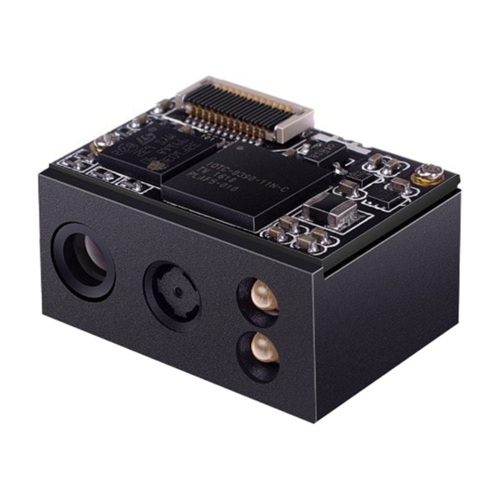
- Page 1 RT206 OEM Scan Engine Integration Guide...
-
Page 2: Table Of Contents
Table of Contents Chapter 1 Introduction..............................1 Overview....................................1 Illumination..................................1 Aimer....................................1 Chapter 2 Installation................................ 2 General Requirements..............................2 ESD....................................2 Dust and Dirt................................2 Thermal Considerations............................. 2 Installation Orientation..............................2 Optics....................................4 Window Placement..............................4 Window Material and Color............................4 Scratch Resistance and Coating..........................5 Window Size.................................5 Ambient Light................................ - Page 3 Chapter 4 Interfaces................................ 11 Host Interface Connector..............................11 Dimensions of the Host Interface Connector (unit: mm)..................12 FFC Cable (unit: mm)...............................13 Communication Interfaces............................14 Control Interfaces................................15 Reset................................... 15 Trigger..................................15 Beeper..................................16 Good Read LED................................ 17 Chapter 5 Development Tools............................18 EVK....................................18...
-
Page 4: Chapter 1 Introduction
Aimer The RT206 has a view finder that produces a solid circle-shaped aiming pattern to help the user to easily position the target barcode within the engine’s field of view to increase scan efficiency. The aiming pattern... -
Page 5: Chapter 2 Installation
Chapter 2 Installation General Requirements ESD protection has been taken into account when designing the RT206 and the engine is shipped in ESD safe packaging. Always exercise care when handling the engine outside its package. Be sure grounding wrist straps and properly grounded work areas are used. -
Page 7: Optics
Optics Window Placement The window should be positioned properly to let the illumination and aiming beams pass through as much as possible and no reflections back into the engine (reflections can degrade the reading performance). The window should be mounted close to the front of the engine (parallel). The maximum distance is measured from the front of the engine housing to the farthest surface of the window. -
Page 8: Scratch Resistance And Coating
Scratch Resistance and Coating Scratch on the window can greatly reduce engine performance. It is suggested to use abrasion resistant window material or coating. Window Size The window must not block the field of view and should be sized to accommodate the illumination envelope shown below. -
Page 9: Ambient Light
FOV Envelope 33.2゜ Illumination Envelope 60゜ Ambient Light The RT206 shows better performance with ambient light and it is well able to handle the flicker in fluorescent lights using 50-60Hz AC power. However, high-frequency pulsed light can result in performance degradation. -
Page 10: Mounting
Mounting The illustrations below show the mechanical mounting dimensions for the RT206. The structural design should leave some space between components. Front View (unit: mm) Side View (unit: mm) -
Page 11: Top View (Unit: Mm)
Top View (unit: mm) Mounting Hole M1.6... -
Page 12: Chapter 3 Electrical Specifications
Chapter 3 Electrical Specifications Power Supply Do not power up the RT206 until it is properly connected. Be sure the power is cut off before connecting a cable to or disconnecting a cable from the host interface connector. Hot-plugging could damage the engine. -
Page 13: Dc Characteristics
DC Characteristics Operating Voltage Ta=25℃ Parameter Description Minimum Typical Maximum Unit Voltage Drain Drain High Level Input Voltage -0.5 Low Level Input Voltage High Level Output Voltage -0.3 Low Level Output Voltage Operating Current Ta=25℃,V =3.3V Operating Current Standby Current Sleep Current 141mA (typical) 10mA... -
Page 14: Chapter 4 Interfaces
Chapter 4 Interfaces Host Interface Connector The following table lists the pin functions of the 12-pin host interface connector on the RT206. PIN1 PIN# Signal Function Not connected. 3.3V power supply. Power-supply ground. TTL level 232 receive data. TTL level 232 transmit data. -
Page 15: Dimensions Of The Host Interface Connector (Unit: Mm)
Dimensions of the Host Interface Connector (unit: mm) The RT206 uses a 12-pin FPC ZIF socket (bottom contact, model: 10051922-1210EHLF) manufactured by FCI. The socket can be connected to a host device with a FFC cable. -
Page 16: Ffc Cable (Unit: Mm)
FFC Cable (unit: mm) A 12-pin FFC cable can be used to connect the RT206 to a host device. The cable design must be consistent with the specifications shown below. Use reinforcement material for the connectors on the cable and reduce cable impedance for reliable connection and stable performance. -
Page 17: Communication Interfaces
Communication Interfaces The RT206 can communicate with the host device via its TTL-232 interface. This interface is applicable to most system architectures. For those requiring RS-232, a TTL-232 to RS-232 conversion circuit is needed. The RT206’s TTL-232 interface supports baud rates from 1200bps to 115200bps; it does not support hardware flow control. -
Page 18: Control Interfaces
(PIN 12) on the host interface connector low for over 10ms causes the RT206 to start a scan and decode session. If barcode is decoded, the RT206 waits for the voltage at the nTrig pin to turn high (or the trigger to be released) after sending the data to the Host. If the trigger is released during a scan attempt, the RT206 immediately stops decoding. -
Page 19: Beeper
Beeper The RT206 provides a pin (Buzz, PIN 9) on the host interface connector that provides a PWM output to an external driver circuit for generating audible feedback to the user to indicate statuses like power up or good read. The PWM output is not strong enough to drive a beeper, thus a beeper driver circuit is needed. -
Page 20: Good Read Led
Good Read LED The RT206 provides a pin (LED, PIN 10) on the host interface connector that can be used by an external driver circuit to drive an LED to indicate a Good Read status. When a good read occurs, the LED pin produces a high level output and then the signal is back to a low level. -
Page 21: Chapter 5 Development Tools
LED & LED driver circuit, and trigger & reset buttons, TTL-232 to RS-232 converter & TTL-232 to USB converter, RS-232 & USB interfaces, etc. The RT206 can be connected to the EVK via a 12-pin FFC cable type 1 (contacts on the same side). Either USB connection or RS-232 connection can...
Need help?
Do you have a question about the RT206 and is the answer not in the manual?
Questions and answers