Table of Contents
Advertisement
Quick Links
Advertisement
Table of Contents

Related Manuals for Best Fitness BFE2


Summary of Contents for Best Fitness BFE2
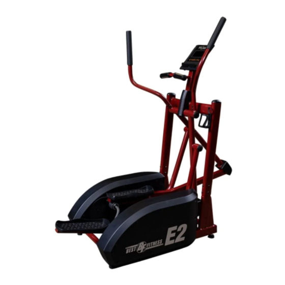
- Page 1 V. BFE2-112718 BFE2 O w n e r ’ s M a n u a l...
-
Page 2: Table Of Contents
Should additional information be required, or should situations arise that are not covered by this manual, the matter should be directed to your local Best Fitness ® representative, or the Service... -
Page 3: Introduction
Best Fitness ® wants to ensure years of quality workouts with your new Elliptical so we recommend that you read this manual carefully and thoroughly to fully understand proper use and maintenance of this product. -
Page 4: Important Safety Information
When using exercise equipment, you should always take basic precautions, includ- ing the following: • Read all instructions before using the BFE2. These instructions are written to ensure your safety and to protect the unit. • Do not allow children on or near the equipment. -
Page 5: Safety Guidelines
safety guidelines Successful resistance training programs have one prominent feature in common ...safety. Resistance training has some inherent dangers, as do all physical activities. The chance of injury can be greatly reduced or completely removed by using correct lifting techniques, proper breathing, maintaining equipment in good working condi- tion, and by wearing the appropriate clothing. -
Page 6: Before You Begin
Locate all hardware bags, labeled Figure 1 through Figure 9, with the exception of Figure 8. Tools have been provided to assist you with assembling the Best Fitness ® If you are missing any hardware bags, please call Best Fitness ® Customer Tech Support... -
Page 7: Assembly Instructions
Assembly of the BFE2 takes professional installers about 1 hour to complete. If this is the first time you have assembled this type of equipment, plan on significantly more time. PRoFESSIoNAl INSTAllERS ARE hIghly REcoMMENDED! however, if you acquire the appropriate tools, obtain assistance, and follow the as- sembly steps sequentially, the process will take time, but is fairly easy. -
Page 8: Assembly
S T E P be careful to assemble all components in the sequence they are presented. Carefully lift the Upright Frame Assembly above the front of the Base Frame. Attach wire harness as shown. NOTE: A second person is required. Slide the Upright Frame onto the Base Frame. - Page 9 S T E P M8 Washer M8 Arc Washer...
- Page 10 S T E P be careful to assemble all components in the sequence they are presented. Insert Right Rocker Arm into Right Swing Arm and install hardware as shown: Insert End Cap into Right Rocker Arm. Insert Left Rocker Arm into Left Swing Arm and install hardware as shown: Insert End Cap into Left Rocker Arm.
- Page 11 S T E P M10 Washer M10 Spring Washer...
- Page 12 S T E P be careful to assemble all components in the sequence they are presented. Connect the Rocker Arms as shown.
- Page 13 S T E P...
- Page 14 S T E P be careful to assemble all components in the sequence they are presented. Connect the Right Foot Pedal to the Right Foot Tube using Six M6x16 Phillips Screw Connect the Left Foot Pedal to the Left Foot Tube using Six M6x16 Phillips Screw...
- Page 15 S T E P...
- Page 16 S T E P be careful to assemble all components in the sequence they are presented. Connect the Foot Tubes as shown.
- Page 17 S T E P...
- Page 18 S T E P be careful to assemble all components in the sequence they are presented. Attach the Water Holder using the hardware shown. Connect the Swing Arm Cover as shown using the hardware shown.
- Page 19 S T E P M5x12 Phillips Bolt M5x12 Phillips Bolt M5x12 Phillips Bolt...
- Page 20 S T E P be careful to assemble all components in the sequence they are presented. Connect the Right Handle Bar using the hardware shown. Connect the Left Handle Bar using the hardware shown.
- Page 21 S T E P M8x16 Allen Bolt M8 Arc Washer...
- Page 22 S T E P be careful to assemble all components in the sequence they are presented. Connect the harness from the Console Frame to the Main Frame then secure using: Three M8x65 Allen Bolt Three M8 Washer Slide the Net Cover Frame onto the Main Frame and secure using: Two M5x8 Phillips Screw Connect the harnesses from the Console to the Console Frame...
- Page 23 S T E P Insert Power Supply here.
-
Page 24: Console Overview
cOnsOle Overview Take a few moments to review the console layout. Below is an overview of the console buttons and their different functions. Display Window Control Buttons... - Page 25 cOnsOle Overview MOde Press the MODE button to set the values for TIME, DISTANCE, CALORIES and PULSE. reset The RESET button clears all preset values to zero except in user programs. Returns to the Training Mode screen. start/stOp Press the START/STOP button to either start or stop a workout. recOvery Press the RECOvERY button to test Heart Rate recovery status.
-
Page 26: Console Operation
cOnsOle OperatiOn setting up the cOnsOle When plugging in the power cord or after having pressed the TOTAL RESET button, GETTING STARTED WITH YOUR MONITOR the DISPLAY WINDOW will reset by activating the LCD completely for 2 seconds followed by a long beep. The room temperature will display shortly. Press Total Reset. - Page 27 ONTH/DAY and CLOCK. PROGRAM PROGRAM function values for TIME, DISTANCE, CALORIES, function values for TIME, DISTANCE, CALORIES, and PULSE by pressing the UP or DOWN button and PULSE by pressing the UP or DOWN button Training in PROGRAM Mode (See page 20 Training in PROGRAM Mode (See page 20 drawing 1 drawing 2...
- Page 28 cOnsOle OperatiOn Manual MOde To access Manual Mode, see the Training Mode Programs section. While in Manual Training in MANUAL Mode conds Mode, press the UP/DOWN buttons to select a ‘LOAD LEvEL’ from 1 to 16. The preset In the MANUAL Mode, you may press the UP load level is 1 and the LOAD readout is flashing on the DISPLAY WINDOW.
- Page 29 nking, press UP or DOWN to n the PROGRAM mode, you may press the UP am MANUAL/PROGRAM/ or DOWN button to select Programs P01- P6. o set. The Monitor will enter The selected Program will be show on screen cOnsOle OperatiOn raining without selection.
- Page 30 cOnsOle OperatiOn user MOde To access User Mode, see the Training Mode Programs section. User Mode allows the user access to create a workout program to tailor fit their exercise requirements. The user can adjust up to 20 workout intervals within the program as well as set custom- ized count-down workout goals.
- Page 31 and MODE button to set. The Monitor will calculate and calendar. button for training. preset Heart Rate value automatically according 2. When Monitor displays abnormally, please to your age setting. (Preset at Age 30). Screen will unplug the adapter and plug-in again. show Heart Rate percentage 55%, 75%, 90% and cOnsOle OperatiOn TARGET.
- Page 32 cOnsOle OperatiOn watt MOde To access Watt Mode, see the Training Mode Programs section. Watt Mode allows the user to output a constant power during a workout. This means that if you pedal quickly, the resistance will decrease, if you pedal slowly the resistance will increase to maintain the Watt value entered.
- Page 33 cOnsOle OperatiOn heart rate (pulse) sensOrs The Heart Rate or ‘Pulse’ in the console’s DISPLAY WINDOW works in conjunction with the heart rate sensors found on the handlebars. To read your pulse place both hands firmly on the heart rate sensors. For the most accurate reading, it is important to use both hands and to temporarily stop moving.
-
Page 34: Monitoring Your Heart Rate
MOnitOring yOur heart rate To obtain the greatest cardiovascular benefits from your exercise workout, it is im- portant to work within your target heart rate zone. The American Heart Association (AHA) defines this target as 60% -75% percent of the Maximum Heart Rate. The Maximum Heart Rate may be roughly calculated by subtracting the user’s age from 220. - Page 35 MOnitOring yOur heart rate fitness safety The Heart Rate chart indicates average rate zones for different ages. A variety of dif- ferent factors (including medication, emotional state, temperature and other con- ditions) can affect the target heart rate zone that is best for you. Your physician or health care professional can help you determine the exercise intensity that is appro- priate for your age and condition.
-
Page 36: Power Input Location
pOwer input lOcatiOn The location of the power input is on the left side of the shroud. See below photo. Plug in Here... - Page 37 nOte...
- Page 38 2009. Best Fitness. All rights reserved. Best Fitness reserves the right to change design and specifications when we feel it will improve the product. Best Fitness machines maintain several patented and patent pending features and designs. All rights reserved on all design patents and utility patents.
Need help?
Do you have a question about the BFE2 and is the answer not in the manual?
Questions and answers