Table of Contents
Advertisement
Quick Links
Rhein Tech Laboratories, Inc.
Client: M/A COM, Inc.
360 Herndon Parkway
Model: M5300 900 MHz Mobile Radio
Suite 1400
ID's: OWDTR-0049-E/3636B-0049
Herndon, VA 20170
Standards: Part 90/RSS-119
http://www.rheintech.com
Report #: 2007163-001
Appendix I:
User Manual
Please refer to the following pages.
44 of 58
Advertisement
Chapters
Table of Contents

Related Manuals for Tyco Electronics M5300 Series


Summary of Contents for Tyco Electronics M5300 Series
- Page 1 Rhein Tech Laboratories, Inc. Client: M/A COM, Inc. 360 Herndon Parkway Model: M5300 900 MHz Mobile Radio Suite 1400 ID’s: OWDTR-0049-E/3636B-0049 Herndon, VA 20170 Standards: Part 90/RSS-119 http://www.rheintech.com Report #: 2007163-001 Appendix I: User Manual Please refer to the following pages. 44 of 58...
- Page 2 Operator’s Manual MM-012125-001 May/07 M/A-COM (Place graphic here) M5300 Series Digital Mobile Radio...
- Page 3 MM-012125-001 MANUAL REVISION HISTORY DATE REASON FOR CHANGE May/07 Initial Release. M/A-COM Technical Publications would particularly appreciate feedback on any errors found in this document and suggestions on how the document could be improved. Submit your comments and suggestions to: Wireless Systems Business Unit or fax your comments to: 1-434-455-6851 M/A-COM, Inc.
-
Page 4: Table Of Contents
MM-012125-001 TABLE OF CONTENTS Page SAFETY SYMBOL CONVENTION....................6 RF ENERGY EXPOSURE INFORMATION ..................7 RF ENERGY EXPOSURE AWARENESS, CONTROL INFORMATION, AND OPERATION INSTRUCTIONS FOR FCC OCCUPATIONAL USE REQUIREMENTS ........ 7 2.1.1 Federal Communications Commission Regulations............7 COMPLIANCE WITH RF EXPOSURE STANDARDS ............. 8 2.2.1 Mobile Antennas...................... - Page 5 MM-012125-001 TABLE OF CONTENTS Page 6.18.2 Disabling Stealth Mode ....................24 6.19 ADJUSTING SIDE TONE AUDIO LEVEL................24 6.20 CHANGE OPERATING MODE....................24 6.21 RECEIVING AND TRANSMITTING VOICE CALLS ............25 6.21.1 Receiving a Voice Call ....................25 6.21.2 Transmitting a Voice Call....................25 6.22 ADJUSTING AUDIO TREBLE LEVEL ...................
- Page 6 MM-012125-001 TABLE OF CONTENTS Page FIGURES Figure 6-1: System Model ........................13 Figure 6-2: Scan Model ........................... 13 Figure 6-3: Typical Display........................17 Figure 6-4: Personality Structure Example ..................... 18 TABLES Table 2-1: Rated Power and Recommended Minimum Safe Lateral Distance ......... 8 Table 6-1: Front Panel Default Controls and Functions................
-
Page 7: Safety Symbol Convention
MM-012125-001 SAFETY SYMBOL CONVENTION The following conventions are used throughout this manual to alert the user to general safety precautions that must be observed during all phases of operation, service, and repair of this product. Failure to comply with these precautions or with specific warnings elsewhere in this manual violates safety standards of design, manufacture, and intended use of the product. -
Page 8: Rf Energy Exposure Information
MM-012125-001 RF ENERGY EXPOSURE INFORMATION RF ENERGY EXPOSURE AWARENESS, CONTROL INFORMATION, AND OPERATION INSTRUCTIONS FOR FCC OCCUPATIONAL USE REQUIREMENTS Before using your mobile two-way radio, read this important RF energy awareness and control information and operational instructions to ensure compliance with the FCC’s RF exposure guidelines. -
Page 9: Compliance With Rf Exposure Standards
MM-012125-001 COMPLIANCE WITH RF EXPOSURE STANDARDS Your MA/COM, Inc. M5300 mobile two-way radio is designed and tested to comply with a number of national and international standards and guidelines (listed below) regarding human exposure to RF electromagnetic energy. This radio complies with the IEEE and ICNIRP exposure limits for occupational/controlled RF exposure environment at duty factors of up to 50% talk-50% listen and is authorized by the FCC for occupational use. -
Page 10: Mobile Antennas
MM-012125-001 2.2.1 Mobile Antennas Install the radio’s antenna (refer to Table 2-1 for applicable antenna part numbers) in the center of the vehicle’s roof. These mobile antenna installation guidelines are limited to metal body motor vehicles or vehicles with appropriate ground planes. The antenna installation should additionally be in accordance with the following. -
Page 11: Operation Safety Recommendations
MM-012125-001 OPERATION SAFETY RECOMMENDATIONS TRANSMITTER HAZARDS The operator of any mobile radio should be aware of certain hazards common to the operation of vehicular radio transmitters. A list of several possible hazards is given: • Explosive Atmospheres – Just as it is dangerous to fuel a vehicle with the motor running, similar hazards exist when operating a mobile radio. -
Page 12: Operating Rules And Regulations
MM-012125-001 OPERATING RULES AND REGULATIONS Two-way FM radio systems must be operated in accordance with the rules and regulations of the local, regional, or national government. In the United States, the M5300 mobile radio must be operated in accordance with the rules and regulations of the Federal Communications Commission (FCC). -
Page 13: Product Description
MM-012125-001 PRODUCT DESCRIPTION Designed to meet the critical demands of utility and public service users, the M5300 mobile provides the latest in digital radio technology. The M5300 is capable of supporting multiple operating modes, ® ® including OpenSky digital operation, EDACS or ProVoice trunked modes, and conventional analog mode. -
Page 14: Operation
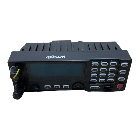
MM-012125-001 OPERATION CH721 FRONT PANEL COMPONENTS The front panel of the control head includes a dot matrix display, controls for menu navigation, an emergency button, three pre-set buttons, a power button/rotary volume dial, and a microphone connector. In addition, the system model control head features a DTMF keypad. Table 6-1 lists all default front panel controls and their functions. -
Page 15: Table 6-1: Front Panel Default Controls And Functions
MM-012125-001 The buttons on the front panel are backlit for operation in a low ambient light level such as nighttime operation. Some buttons also flash to provide feedback of various operating conditions. In addition, the front panel contains a light-level sensor that samples ambient light levels for automatic display and button backlight brightness adjustments. -
Page 16: Power Up And Volume Control
MM-012125-001 POWER UP AND VOLUME CONTROL 6.2.1 Power Up 1. Rotate the Power/Volume Control knob clockwise to power on the radio. The display will illuminate when the radio powers up. 2. Wait for the power-up sequence to complete, which takes approximately ten (10) seconds. During this time, if enabled for auto registration, the radio is provisioned with a customized user personality designed for the user’s specific needs by the OpenSky network administrator. -
Page 17: Log Off The Network
MM-012125-001 The User ID may be remembered from the previous log-in. (Refer to Section 6.5 for further details regarding log-off commands.) The password will be established before the radio is put into operation. Contact the local OpenSky network administrator for more information. If necessary, contact radio system administration personnel for log-in assistance and/or radio-specific log-in instructions. -
Page 18: Radio Status Icons
MM-012125-001 Figure 6-3: Typical Display RADIO STATUS ICONS Status Icons indicate the various operating characteristics of the radio. The icons show operating modes and conditions (see Table 6-2). The location of icons on the display may vary depending on configuration. Table 6-2: ICONS and Descriptions ICON DESCRIPTION... -
Page 19: Talk Groups
MM-012125-001 Profile 1 Profile 2 Profile 3 TG a TG a TG d TG b TG d TG e TG c TG g TG f TG x TG h TG y TG i TG z TG = Talk Group Figure 6-4: Personality Structure Example 6.10.2 Talk Groups A talk group represents a set of users that regularly need to communicate with one another. -
Page 20: Basic Menu Structure
MM-012125-001 NAME TONE DESCRIPTION Selective Alert Only played once to indicate a selective alert has been four short tones Received receive Emergency Alert Tone three (3) short beeps Sounds when an emergency alert is declared Emergency Cleared one long low-pitched tone Sounds when an emergency is cleared Tone Ringing is repeated every four (4) seconds until the call... -
Page 21: Table 6-4: Basic Menu Structure
MM-012125-001 Table 6-4: Basic Menu Structure Radio Displays Menu Name Usage Notes (top and bottom lines) To/From Dwell Display registration, RF sync and Engineering Display transceiver status codes (Menu may not be Displays radio system connection data. For engineering use. available per bit-error rates programming.) - Page 22 MM-012125-001 Radio Displays Menu Name Usage Notes (top and bottom lines) See Previous Page current scan mode to turn scan on and off. Press MENU to return to Scan Mode “ScnModeMenu” dwell display. talk group “<” Talk group to choose a talk group for locking/unlocking. Press Lock Out “LockOutMenu”...
-
Page 23: Dual-Tone Multi-Frequency
MM-012125-001 6.13 DUAL-TONE MULTI-FREQUENCY Dual-Tone Multi-Frequency (DTMF) is the system used by touch-tone telephones. DTMF assigns a specific tone frequency to each key so a microprocessor can easily identify its activation. The radio supports DTMF with a system model control head (Figure 6-1). This allows for specific tasks such as entering a user ID and password, or selective calling. -
Page 24: Changing The Active Profile
MM-012125-001 6.15 CHANGING THE ACTIVE PROFILE The radio can store up to sixteen (16) standard profiles, one of which is the currently active profile. To change the currently active profile: 1. Press up or down using until “ProfileMenu” is displayed. 2. -
Page 25: Enabling Stealth Mode
MM-012125-001 6.18.1 Enabling Stealth Mode 1. Using , scroll through the menu until “StealthMenu” appears. 2. To immediately turn stealth mode on, press up or down with 3. To turn stealth mode off, press any button on the radio’s front panel. 6.18.2 Disabling Stealth Mode Pressing any radio button other than the mic’s PTT button or the emergency button on front panel will immediately turn stealth mode off. -
Page 26: Receiving And Transmitting Voice Calls
MM-012125-001 6.21 RECEIVING AND TRANSMITTING VOICE CALLS As soon as the radio completes the startup/log-on/provision/self-test sequence and registers on the OpenSky network, voice calls from talk groups in the active profile will be audible. 6.21.1 Receiving a Voice Call No action is required to receive a voice call. The display responds to incoming voice calls as follows: •... -
Page 27: Talk Group Lock Out
MM-012125-001 2. Use to toggle between “On” and “Off.” When intercom mode is turned on: • Incoming voice calls will override intercom communications for the duration of the voice call. The radio and associated control heads will remain in intercom mode and intercom communications will resume when the voice call ends. -
Page 28: Lock Out A Talk Group
MM-012125-001 6.24.1 Lock Out a Talk Group 1. Use to scroll through the menu until “LockOutMenu” appears in the bottom line of the display. The name of a talk group in the currently active profile will appear in the top line. 2. -
Page 29: Checking Or Changing Active Scan Mode
MM-012125-001 Table 6-6: Scan Modes SCAN EXPLANATION MODE Eliminates distractions. Full communications (transmit and receive) on selected talk group. No Scan No calls received from other talk groups. The user can scan all talk groups in the active profile that are not locked out as long as there is demand on the site. -
Page 30: Making Selective Calls
MM-012125-001 7. Other (non-priority) 6.25.2.1 Changing Scanning Priority Follow this procedure to set talk groups in the current profile as the Priority 1 or Priority 2 talk group: 1. Use to scroll through the menu until “Priority1” or “Priority2” appears in the bottom line of the display (Priority1 group has higher priority than the Priorty2 group. -
Page 31: Speed Dialing A Selective Call
MM-012125-001 6.26.2 Speed Dialing a Selective Call Speed dial numbers are defined and provisioned by the OpenSky network administrator and cannot be manually entered into the radio by the user. Contact the administrator if changes to the speed dial list are required. 1. -
Page 32: Receiving Messages
MM-012125-001 3. When the desired speed-dial number appears, press the MENU button to activate the selection. 4. Choose and send the message. Keypad Method (System Model Control Head): To select the destination radio’s User ID using the keypad, perform the following: 1. -
Page 33: Defining Pre-Programmed Messages
MM-012125-001 Displaying Received Messages 1. Using , scroll through the menu until “AlertsRecvd” (Alerts Received) appears in the bottom line of the display. “No alerts” or the last received (newest) message appears in the display. It is preceded by the time the message was received, and the sender’s name/alias. 2. -
Page 34: Declaring An Emergency Call Or Alert
MM-012125-001 before the infrastructure assets are automatically taken away. Because an emergency call is handled on a talk group, it is received by all radios and consoles monitoring the talk group. An emergency alert is a data message sent by the radio to the MIS console (or any console capable of receiving it). -
Page 35: Silent Emergency
MM-012125-001 6.29.2 Silent Emergency When this feature is enabled and an emergency call or alert is declared by pressing the emergency button, the radio will not play a tone and will display an abbreviated emergency message (default is EBA). This feature is enabled or disabled via programming or via the menu. -
Page 36: Dismissing An Emergency Call
MM-012125-001 A radio declaring an emergency on a talk group has a “hot” mic time period of typically ten (10) seconds just after it declares the emergency. This time period may be adjusted by system or network administration personnel on a per radio basis. 6.29.5 Dismissing an Emergency Call An emergency is dismissed for a configurable amount of time only (default = 5 minutes). -
Page 37: Manual Encryption (System Model)
MM-012125-001 6.30.2 Manual Encryption (System Model) Two or more users can manually encrypt a call, if enabled, without an established encrypted talk group. A pre-determined key is required at each radio. The key must be pre-determined by the users prior to making a manually encrypted call on a talk group and is entered into the radio using the keypad. -
Page 38: Dynamic Regrouping
MM-012125-001 • Intercom mode Presets are saved and restored to/from non-volatile memory. Changing the User ID (login in as a different user) will clear the presets since they are stored on a per-user basis. Changing control heads will not recall presets for the previous control head. -
Page 39: Basic Troubleshooting
MM-012125-001 BASIC TROUBLESHOOTING If the radio is not operating properly, check Table 7-1 for likely causes. For additional assistance, contact a qualified service technician. Table 7-1: Basic Troubleshooting SYMPTOM CAUSE SOLUTION Test the connection to the vehicle power Radio will not turn on. No power. - Page 40 MM-012125-001 SYMPTOM CAUSE SOLUTION In multiple control head Control head configurations, another user is randomly changes None operating the radio from another display. control head. Encrypted calls cannot Contact system administrator to request Not authorized to use. be made. encryption privileges. Screen displays: The radio network ID has not Contact system administrator.
-
Page 41: Technical Assistance
MM-012125-001 TECHNICAL ASSISTANCE The Technical Assistance Center's (TAC) resources are available to help with overall system operation, maintenance, upgrades and product support. TAC is the point of contact when answers are needed to technical questions. Product specialists, with detailed knowledge of product operation, maintenance and repair provide technical support via a toll-free (in North American) telephone number. -
Page 42: Keypad Remapping
MM-012125-001 KEYPAD REMAPPING If the keys have been remapped to provide new functions, fill in the following template for future reference. Button Function Button Function Emergency Preset A Preset B Preset C • Rocker •• Rocker Rocker Rocker MENU OPT/OPTION CLR/CLEAR SCAN... -
Page 43: Warranty
MM-012125-001 10 WARRANTY M/A-COM, Inc. (hereinafter "Seller") warrants to the original purchaser for use (hereinafter "Buyer") that Equipment manufactured by or for the Seller shall be free from defects in material and workmanship, and shall conform to its published specifications. With respect to all non-M/A-COM Equipment, Seller gives no warranty, and only the warranty, if any, given by the manufacturer shall apply. - Page 44 MM-012125-001 This page intentionally left blank.
- Page 45 Tyco Electronics Wireless Systems Segment 221 Jefferson Ridge Parkway Lynchburg, Virginia 24501 (Outside USA, 1-434-385-2400) Toll Free 1-800-528-7711 www.macom-wireless.com Printed in U.S.A.
- Page 46 Installation and Product Safety Manual MM-012137-001 May/07 M/A-COM M5300 Mobile Radio 900 MHz Half-Duplex Remote-Mount Mobile Radio with CH-721 Scan and System Control Heads...
- Page 47 M/A-COM Technical Publications would particularly appreciate feedback on any errors found in this document and suggestions on how the document could be improved. Submit your comments and suggestions to: Tyco Electronics Wireless Systems Segment M/A-COM, Inc. or fax your comments to: 1-434-455-6851...
- Page 48 MM-012137-001 TABLE OF CONTENTS Page REGULATORY AND SAFETY INFORMATION..................6 SAFETY SYMBOL CONVENTIONS....................6 RF ENERGY EXPOSURE AWARENESS AND CONTROL INFORMATION FOR FCC OCCUPATIONAL USE REQUIREMENTS..................6 1.2.1 Federal Communications Commission Regulations............... 7 COMPLIANCE WITH RF EXPOSURE STANDARDS..............7 1.3.1 Mobile Antennas ........................
- Page 49 MM-012137-001 (Continued) TABLE OF CONTENTS Page CONTROL HEAD INSTALLATION ....................33 7.3.1 General Information......................33 7.3.2 Control Head Mechanical Installation ..................35 7.3.3 Control Head-to-Radio CAN Cable Connections ..............37 7.3.4 Control Head Power Cable Installation ................39 MICROPHONE ATTACHMENT ......................42 SPEAKER INSTALLATION ........................43 10 M5300/M7300 OPTION CABLE .......................44 11 GPS NMEA-FORMATTED SERIAL DATA CONNECTION...............47 12 INITIAL POWER-UP TEST........................48 13 PERFORMANCE TESTS...........................49...
- Page 50 MM-012137-001 FIGURES Page Figure 5-1: Typical Remote-Mount Mobile Radio Installation in a Standard Passenger Vehicle ..21 Figure 5-2: M5300 Remote-Mount Mobile Radio — Front and Rear Views ........22 Figure 6-1: Recommended Antenna Mounting Locations with Antenna Part Numbers..... 24 Figure 7-1: Mounting Bracket with Dimensions (Radio Not Shown)..........
-
Page 51: Regulatory And Safety Information
MM-012137-001 REGULATORY AND SAFETY INFORMATION SAFETY SYMBOL CONVENTIONS The following conventions are used in this manual to alert the user to general safety precautions that must be observed during all phases of operation, installation, service, and repair of this product. Failure to comply with these precautions or with specific warnings elsewhere violates safety standards of design, manufacture, and intended use of the product. -
Page 52: Federal Communications Commission Regulations
MM-012137-001 both workers and the general public. These recommended RF exposure levels include substantial margins of protection. All two-way radios marketed in North America are designed, manufactured, and tested to ensure they meet government-established RF exposure levels. In addition, manufacturers also recommend specific operating instructions to users of two-way radios. -
Page 53: Mobile Antennas
MM-012137-001 Table 1-1: Recommended Minimum Safe Lateral Distance from Transmitting Antenna RECOMMENDED MINIMUM LATERAL HUMAN BODY DISTANCE FROM TRANSMITTING ANTENNA ANTENNA (Distance in Centimeters) PART NUMBER ANTENNA DESCRIPTION (Catalog Number) CONTROLLED UNCONTROLLED ENVIRONMENT ENVIRONMENT 900 MHz GPS Combo, Elevated- AN-025177-004 Feed, Rooftop-Mount;... -
Page 54: Common Hazards
MM-012137-001 The information listed above provides the user with information needed to make him or her aware of a RF exposure, and what to do to assure that this radio operates within the FCC exposure limits of this radio. COMMON HAZARDS The operator of any mobile radio should be aware of certain hazards common to the operation of vehicular radio transmissions. -
Page 55: Safe Driving Recommendations
MM-012137-001 SAFE DRIVING RECOMMENDATIONS The American Automobile Association (AAA) advocates the following key safe driving recommenda- tions: • Read the literature on the safe operation of the radio. • Keep both hands on the steering wheel and the microphone in its hanger whenever the vehicle is in motion. -
Page 56: Operating Tips
MM-012137-001 Under U.S. law, operation of an unlicensed radio transmitter within the jurisdiction of the United States may be punishable by a fine of up to $10,000, imprisonment for up to two (2) years, or both. CAUTION OPERATING TIPS The following conditions tend to reduce the effective range of two-way radios and should be avoided whenever possible: •... -
Page 57: Specifications
MM-012137-001 SPECIFICATIONS GENERAL 2.0 x 6.9 x 9.2 inches (5.1 x 17.5 x 23.4 centimeters) Dimensions, Remote-Mount Mobile Radio: (Height x Width x Depth) (Includes bracket but not space required for cables) 2.4 x 6.9 x 3.9 inches (6 x 17.5 x 10 centimeters) Dimensions, Control Head: (Height x Width x Depth) (Does not include bracket and mounting screws) -
Page 58: Regulatory
MM-012137-001 70 dB minimum at 12.5 kHz Receiver Intermodulation Rejection: 300 to 3000 Hz (with <3% audio distortion) Audio Frequency Response: 15 watts RMS maximum into 4-ohm external speaker; Audio Output Power (Control Head): 1 watt into 4-ohm headset Voice-Coding Method: OTP Mode: Advanced Multi-Band Excitation (AMBE™) EDACS, ProVoice and P25 Modes:... -
Page 59: Introduction
MM-012137-001 INTRODUCTION GENERAL DESCRIPTION The M5300 mobile radio is a high-performance half-duplex digital mobile radio. It can operate on 900 MHz OpenSky trunked radio networks using the OpenSky Trunking Protocol (OTP). Other future radio operating modes include talk-around communications in accordance with the APCO Project 25 phase I standard, and conventional FM repeater-based and FM talk-around voice communications in accordance with the TIA/EIA-603 conventional land-mobile radio standard. - Page 60 MM-012137-001 separately fused. When the control head is powered-up by the operator, it “wakes up” the radio by transmitting data to the radio via the CAN link. The radio provides half-duplex voice and data communications. Voice communications are accomplished via a “push-to-talk” (PTT) type microphone and a speaker connected to the control head. For data communications, the radio has an industry-standard 9-pin serial interface port for connecting optional data-type equipment, such as a Mobile Data Terminal (MDT), a laptop PC, a third-party display, or a key-entry device.
-
Page 61: Related Documents
MM-012137-001 RELATED DOCUMENTS The following documents contain additional information: • OpenSky Quick Guide: MM-(TBD) • OpenSky Operator’s Manual: MM-012125-001 (available at www.macom-wireless.com) • Maintenance Manual: MM012126-001 REPLACEMENT PARTS Replacement parts can be ordered through M/A-COM’s Customer Resource Center. To order replacement parts through the Customer Resource Center, call, fax or email our ordering system: North America: •... -
Page 62: Unpacking And Checking The Equipment
MM-012137-001 UNPACKING AND CHECKING THE EQUIPMENT MATERIALS A typical set of materials for a remote-mount M5300 mobile radio installation includes: • Remote-Mount 900 MHz Mobile Radio, part number RU-144750-181 • CH-721 Scan Control Head, part number CU23218-0002 (Catalog number MAMV-CP9E) CH-721 System Control Head, part number CU23218-0004 (Catalog number MAMV-CP9F) •... - Page 63 MM-012137-001 Table 4-2: Additional Options and Accessories for M5300 Mobile Radios PART NUMBER DESCRIPTION Antenna, 900 MHz GPS Combo, Elevated-Feed Rooftop-Mount, 3 dBd Gain, with NMO Mounting Base, 15-foot (4.6-meter) RG-58 A/U (or AN-025177-004 equivalent) Low-Loss RF Cable, Male TNC RF Connector, 16.4-foot (5-meter) RG174/U (or equivalent) GPS RF Cable with Male SMA RF Connector;...
-
Page 64: Material Inspection
MM-012137-001 Table 4-3: Additional Options and Accessories for CH-721 Control Heads PART NUMBER DESCRIPTION MAMROS0075-R1210 Cable, DC Power; 12-AWG, 10-Foot, Right-Angle Connector MAMROS0075-R1220 Cable, DC Power; 12-AWG, 20-Foot, Right-Angle Connector MATERIAL INSPECTION After removal from the carton, examine the radio, control head and other components for broken, damaged, loose or missing parts. -
Page 65: Planning The Installation
MM-012137-001 PLANNING THE INSTALLATION GENERAL INFORMATION Figure 5-1 illustrates a typical remote-mount radio installation. Before starting, plan the installation carefully so it will meet the following requirements: • The installation is safe for the operator and passengers within the vehicle. •... - Page 66 MM-012137-001 MOBILE ANTENNA GPS ANTENNA CONTROL HEAD NOTE: SEE TEXT FOR WIRING OF DC POWER CABLE. M5300 TRUNK- MOUNT MOBILE RADIO VEHICLE BATTERY IN-LINE FUSE HOLDER AND FUSE (30-AMP) GROMMET (Mounted in vehicle’s firewall) FUSE BLOCK CAN CABLE (To/From Control Head) SPEAKER RED 10-AWG WIRE (Carries DC power from fuse...
- Page 67 MM-012137-001 FRONT VIEW REAR VIEW (Shown Without Any Installation-Related Cables) (image not available) Figure 5-2: M5300 Remote-Mount Mobile Radio — Front and Rear Views...
-
Page 68: Locating Components
MM-012137-001 LOCATING COMPONENTS Plan the mounting locations of all components (radio, control head, antenna, and cables) and determine the routes for all wiring and cables. Particularly consider the connection of the radio for planning purposes. • Determine the customer’s preferences, if any, for location of components. Comply with these preferences as long as they are consistent with safety recommendations and guidelines presented in this manual, and other generally accepted professional radio installation practices. -
Page 69: Antenna Installation
MM-012137-001 ANTENNA INSTALLATION ANTENNA MOUNTING LOCATIONS At this time, review all information presented in the REGULATORY AND SAFETY INFORMATION section of this manual (begins on page 6). A transmitting antenna must be installed in accordance with the guidelines presented in the REGULATORY AND SAFETY INFORMATION section. Use Table 1-1 on page 8 and Figure 6-1 below as a guide for determining the best possible mounting configuration/location in order to reduce human exposure to radio frequency (RF) electromagnetic energy during transmit mode. -
Page 70: Direct Center Or Center-Rear Of Rooftop
MM-012137-001 6.1.1 Direct Center or Center-Rear of Rooftop The center of the vehicle’s roof is the best location for a rooftop-mount antenna (location in Figure 6-1). For optimal performance, the mounting area under the antenna must be a flat with a minimum radius of six (6) inches of metal ground plane. -
Page 71: Install And Connect The Gps Antenna (Required Only If Radio Has Gps Receiver Option)
MM-012137-001 A unity-gain antenna is tuned for maximum performance (i.e., minimum reflection) per the test procedures presented in Section 13. Other antennas used with the M5300 are factory-tuned and therefore do not require tuning in the field. 4. The antenna cable is connected to the radio’s TNC receptacle-type (female) RF connector per a procedure presented later in this manual. -
Page 72: Remote-Mount Radio Installation
MM-012137-001 REMOTE-MOUNT RADIO INSTALLATION MOUNTING THE RADIO This section provides details on mounting the mobile radio in the vehicle. See Figure 5-2 and refer to the respective wiring diagram at the end of this manual as necessary. Control head installation procedures are included in Section 7.3 which begins on page 33. - Page 73 MM-012137-001 the rear, left and right sides of the radio, and at least (2) inches of clearance is recommended at the front of the radio. As illustrated in Figure 7-1, the bracket is left-to-right symmetrical and the shortest portion of its side rails are at the rear.
-
Page 74: Inserting The Radio Into The Mounting Bracket
MM-012137-001 is recommended. Sheet metal screws should never be used. The bracket has four (4) available mounting holes, and all four must be used to secure the bracket to its mounting surface. The following mounting procedure is recommended: 1. Using the mounting bracket (part of item 1 in Table 4-1 on page 17) as a template, and/or the dimensional information shown in Figure 7-1, mark and drill four (4) mounting holes into the mounting surface as required per the type of hardware used. -
Page 75: Radio Dc Power Installation
MM-012137-001 RADIO DC POWER INSTALLATION Refer to the wiring diagram at the end of this manual as necessary when performing wiring procedures presented in this section. For specific information on wiring the control head’s power, see Section 7.3.4 on page 39. 7.2.1 Overview of On/Off Power Wiring Configurations Radio on/off power control is accomplished by the control head, except in the case of a data-only radio... - Page 76 MM-012137-001 ground connection). It is supplied with waterproof fuse holders, AGC-type fuses, and non-insulated ring terminals. The following installation procedures are recommended: 7.2.2.1 Black Wire Connection (Ground Wire) 1. Connect the radio’s DC Power Cable to the radio by mating its 3-pin connector to the radio’s 3-pin power cable connector as follows: Visually align the key and firmly push and turn the outer locking ring clockwise until it stops.
- Page 77 MM-012137-001 Do not install any wiring or fuse holder over or in the near vicinity of the vehicle’s engine. Excessive engine heat can cause permanent damage to these components and can lead to intermittent electrical connection to the battery. CAUTION Before making connections to the battery’s positive post, carefully disconnect the battery’s negative (ground) cable(s).
-
Page 78: Control Head Installation
MM-012137-001 1. Route the 20-foot white wire of the radio’s DC Power Cable to the location of the vehicle’s switched power source connection point, typically identified as “Accessory” power. Route the wire through channels in the vehicle to the location of the battery. Remove interior panels, door kick panels, etc., as necessary. - Page 79 MM-012137-001 12-Button Keypad Option Button Menu Button Clear Button Figure 7-3: CH-721 System Model Control Head Front Panel The CH-721 control heads feature a large easy-to-read 3-line graphical vacuum fluorescent display, an on/off/volume control knob, menu controls and buttons, trunking mode buttons, an emergency/home button, a scan on/off/volume control, and three (3) preset buttons.
-
Page 80: Control Head Mechanical Installation
MM-012137-001 In a mobile installation, more than one control head can be connected to one mobile radio for multi-head installations. A multi-head installation may be required in a vehicle such as a fire truck or any large vehicle where more than one operator may require use of the radio. Multi-head installations also provide other benefits such as intercom functionality between different operator positions. - Page 81 MM-012137-001 Pedestal shown For a “hanging” control head attached to a CH-721 installation, the pedestal can Scan model control be attached to the top of the head (Head is not head via threaded holes in included with Mounting the top of the head’s case. Pedestal This figure...
-
Page 82: Control Head-To-Radio Can Cable Connections
MM-012137-001 and then into the threaded hole in the side of the control head. This hardware is included with Mounting Bracket Kit. The lockwasher should be adjacent to the screw head and the flat washer should be adjacent to the bracket. Turn each screw clockwise as observed from the head of the screw. - Page 83 MM-012137-001 Figure 7-8: Typical CAN Link Connections for a Multi-Control Head Installation Both the radio and the control head have two CAN ports to support “daisy-chaining” of multiple control heads or other CAN devices. Figure 5-2 on page 22 shows the radio’s two CAN port connectors, which are located near the center of the radio’s rear panel.
-
Page 84: Control Head Power Cable Installation
MM-012137-001 4. Mate this other end of the cable to one of the two CAN port connectors on the rear panel of the radio. 5. Mate another CAN Terminator to the other CAN port connector on the rear panel of the radio. This action makes the CAN termination at the radio-end of the CAN link. - Page 85 MM-012137-001 7.3.4.2 Connect DC Power Cable’s White Wire A review of the information presented in Section 7.2.1 (page 30) may be beneficial at this time. As required per the chosen power-up configuration, connect the white wire by following one of the three procedures presented in the respective sub-section that follows.
- Page 86 MM-012137-001 2. Cut a short section (6 to 8 inches) off the end of the white wire and strip the ends. 3. Obtain one of the waterproof (HFB-type) fuse holders included with the control head’s DC Power Cable, and crimp one half of it to one end of the short section of wire. 4.
-
Page 87: Microphone Attachment
MM-012137-001 MICROPHONE ATTACHMENT There are several versions of microphones available for use with the radio. Each has a 17-pin flush-mount type connector that mates with the mic connector on the front panel of the control head. The mic’s connector includes a captive thumbscrew that secures it to the mic connector on the front panel of the control head. -
Page 88: Speaker Installation
MM-012137-001 SPEAKER INSTALLATION Select a location for the speaker that will allow for proper listening range with a moderate volume setting. Total speaker cable length (of both cables) is approximately five (5) feet. Therefore, to include service loops in the cables, the speaker must be mounted within approximately 4.5 feet of the control head. 1. -
Page 89: M5300/M7300 Option Cable
MM-012137-001 10 M5300/M7300 OPTION CABLE The M5300/M7300 Option Cable CA-012349-001 connects to the radio’s 44-pin I/O cable connector. It breaks out into several smaller standardized connectors. This allows straightforward access to all external I/O interfaces provided by the radio. It also helps speed radio removal and re-installation time when required. - Page 90 MM-012137-001 Table 10-1: M5300/M7300 Option Cable CA-012349-001 Interconnections 44-PIN I/O CABLE SIGNAL NAME TO/FROM DESCRIPTION CONNECTOR SPKR1 P2 pin 1 Speaker Audio Output 1 (Not used in a remote-mount radio installation) SPKR1 P2 pin 1 SPKR2 P2 pin 2 Speaker Audio Output 2 (Not used in a remote-mount radio installation) SPKR2 P2 pin 2...
- Page 91 MM-012137-001 Table 10-1: M5300/M7300 Option Cable CA-012349-001 Interconnections 44-PIN I/O CABLE SIGNAL NAME TO/FROM DESCRIPTION CONNECTOR IGNITION (no connection) Unused/Spare ignition sense input. — (no connection) This pin of P1 is not used/not connected. — (no connection) This pin of P1 is not used/not connected. —...
-
Page 92: Gps Nmea-Formatted Serial Data Connection
MM-012137-001 11 GPS NMEA-FORMATTED SERIAL DATA CONNECTION To obtain GPS NMEA-formatted serial data from the radio, use of the M5300/M7300 Option Cable CA-012349-001 is required. Follow this procedure to complete the GPS NMEA-formatted serial data connections: 1. Obtain M5300/M7300 Option Cable CA-012349-001. Each “leg” of this cable is approximately 65 inches long (166 centimeters). -
Page 93: Initial Power-Up Test
MM-012137-001 12 INITIAL POWER-UP TEST 1. At the radio’s main waterproof (HFB-type) fuse holder installed near the vehicle battery, insert the 15-amp AGC-type fuse that was included with the radio’s DC Power Cable. 2. Tie and stow the fuse holder as necessary to prevent excess vibration/movement. 3. -
Page 94: Performance Tests
MM-012137-001 13 PERFORMANCE TESTS This section includes procedures to verify the performance of the radio installation’s mobile antenna system. The tests require a peak-power reading wattmeter to measure RF power. There are three procedures in this section: • Changing Operating Mode for Tests •... -
Page 95: Required Test Equipment
MM-012137-001 3. Toggle the Ramp Control until OTP (or M: NM for mode = normal) appears in the top line of the display. 4. Confirm the OTP selection by pressing the MENU button, then toggling the Ramp Control once (to select Y for Yes), followed by pressing the MENU button again. -
Page 96: Transmitting Into The Mobile Antenna
MM-012137-001 Vehicle-Mounted 700/800 MHz Antenna TNC Male to N Female M5300 Coaxial Jumper Cable Mobile Radio (Rear View) N-Type to TNC-Type Adaptor Wattmeter Radio’s DC NOTE: CAN cable Power Cable connections not indicated. 3-Pin Connectors Installation’s DC Slug Power Cable (25 W, 400–... - Page 97 MM-012137-001 It is recommended that a test talk group be allocated for this testing. Otherwise, interference with other radio users in the system may occur. Also, during transmissions, always observe the RF exposure-related safety information presented in Section 1.2 on (begins on page 6). A peak-power reading RF wattmeter equivalent to the wattmeter specified in Table 13-1 must be used.
- Page 98 MM-012137-001 14. Disconnect the coaxial cable jumper and wattmeter. 15. Permanently connect the cable from the vehicle-mounted 900 MHz antenna to the radio’s antenna cable by mating the two TNC connectors together. Use two pairs of slip-jaw pliers to gently tighten this connection.
-
Page 99: Test Performance Data Form
MM-012137-001 13.5 TEST PERFORMANCE DATA FORM Clip Here Enter the information requested on this data collection form. Clip this form and file it as a permanent record of the tested performance of the M5300 mobile radio installation. Mobile Radio Serial Number Antenna Make and Model Numbers Date of Test Company Performing Installation... -
Page 100: Complete The Installation
MM-012137-001 14 COMPLETE THE INSTALLATION Double-check the following items before considering the installation completed: • Verify all newly installed mechanical hardware is mounted securely and all respective mounting hardware is tight. • Verify all electrical interconnections are connected properly and the associated connector attachment hardware is tight. -
Page 101: Warranty
MM-012137-001 15 WARRANTY A. M/A-COM, Inc. (hereinafter "Seller") warrants to the original purchaser for use (hereinafter "Buyer") that Equipment manufactured by or for the Seller shall be free from defects in material and workmanship, and shall conform to its published specifications. With respect to all non-M/A-COM Equipment, Seller gives no warranty, and only the warranty, if any, given by the manufacturer shall apply. -
Page 102: Installation Wring Diagram: M5300 Mobile Radio With Ch-721 Control Head
MM-012137-001 16 INSTALLATION WRING DIAGRAM: M5300 MOBILE RADIO WITH CH-721 CONTROL HEAD DRAWING NOT AVAILABLE. WIRING DIAGRAM M5300 Mobile Radio with CH-721 Control Head (AA-TBD Rev. -) - Page 103 Installation Wiring Diagram Inside Tyco Electronics Wireless Systems Segment 221 Jefferson Ridge Parkway Lynchburg, Virginia 24501 (Outside the USA, 1-434-385-2400) Toll Free 1-800-528-7711 www.macom-wireless.com Printed in U.S.A.
Need help?
Do you have a question about the M5300 Series and is the answer not in the manual?
Questions and answers