Table of Contents
Advertisement
Quick Links
Advertisement
Chapters
Table of Contents

Related Manuals for PVA SPP

Summary of Contents for PVA SPP
- Page 1 INNOVATION. PRECISION. EXCELLENCE. Servo Piston Pump Manual Revision A...
- Page 2 SPP Operation Manual This document is based on information available at the time of its publication. While efforts have been made to ensure the contents of this manual are accurate, the information contained herein does not purport to cover all specific details or variations in hardware, or to provide for every possible contingency in connection with installation, operation, or maintenance.
-
Page 3: Table Of Contents
SPP Operation Manual Table of Contents Introduction ......................4 PVA Contact Information ......................4 Document History ........................4 Safety ............................5 System Description ........................7 Maintenance ......................8 Remove the Pump ........................8 Pump Maintenance ......................... 13 Install Pump ..........................27 Technical Specifications .................. 30 Shot Volume .......................... -
Page 4: Introduction
Before you operate this system, read the operation and setup manual. This will help you to become familiar with the product and ensure successful operation. If any questions or problems arise, contact PVA’s Technical Support department. PVA Contact Information Main Office... -
Page 5: Safety
SPP Operation Manual Safety Certain warning symbols are affixed to the machine and correspond to notations in this manual. Before operating the system, identify these warning labels and read the notices described below. Not all labels may be used on any specific system. - Page 6 SPP Operation Manual Do not smoke near the machine. Always have a fire extinguisher available for emergency use. Before performing any repairs or maintenance to the system, turn off power and lock out the power disconnect switch. Warning notices are used to emphasize that hazardous voltages, current, temperatures, or other conditions that could cause personal injury exist in this equipment or may be associated with its use.
-
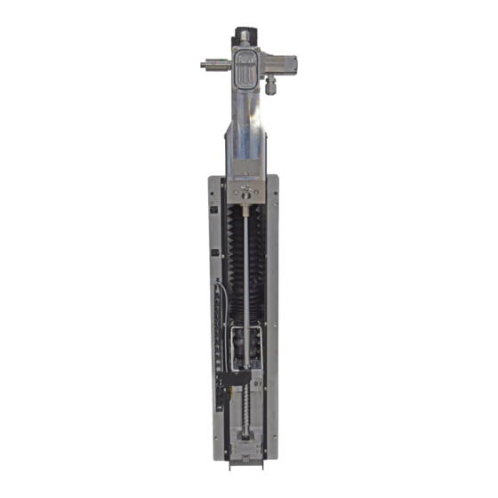
Page 7: System Description
SPP Operation Manual System Description PVA’s SPP Servo Piston Pump system is the ideal choice for precise metered dispensing of heavily filled and abrasive materials. The SPP’s piston displacement design is equipped with a tungsten carbide sleeve that provides a zero dead space shot meter and long service life under adverse conditions. -
Page 8: Maintenance
SPP Operation Manual Maintenance Remove the Pump Prior to removing the pump, it is important to relieve all pressure in the lines. This will ensure a safe and cleanly removal of the pump. 1. Disable the pump. Figure 1: Disable Pump 2. -
Page 9: Figure 3: Dispense
SPP Operation Manual 3. Select the Dispense button. Figure 3: Dispense 4. Turn the pressure off on the tank. Note: The main air must be turned off. Figure 4: Turn Main Air Off Page 9 of 34 Revision A May 2021... -
Page 10: Figure 5: Remove Hoses From Spp
SPP Operation Manual 5. Remove the hoses from the top and side of the SPP. Figure 5: Remove Hoses from SPP 6. Disconnect the power transducer cable. Figure 6: Disconnect Power Transducer Cable Page 10 of 34 Revision A May 2021... -
Page 11: Figure 7: Remove Air Lines
SPP Operation Manual 7. Remove all airlines. Figure 7: Remove Air Lines 8. Use a 3 mm hex key to remove the two front screws on both sides of the SPP. Figure 8: Remove Front Screws Page 11 of 34... -
Page 12: Figure 9: Remove Front Bolts
SPP Operation Manual 9. Use a 5 mm hex key to remove the M6 bolts from the front of the SPP. Figure 9: Remove Front Bolts 10. Remove the SPP from the Endurance cart. Figure 10: Remove SPP from Endurance... -
Page 13: Pump Maintenance
SPP Operation Manual Pump Maintenance 1. Push the metering rod to discard the excess material. Figure 11: Push Rod to Discard Material 2. Use a 6 mm hex key to remove the four M6 screws from the upper manifold block. -
Page 14: Figure 13: Separate Sleeve Rod Assembly
SPP Operation Manual 3. Separate the sleeve rod assembly. Figure 13: Separate Sleeve Rod Assembly 4. Remove the piston from the sleeve. Figure 14: Remove Piston from Sleeve Page 14 of 34 Revision A May 2021... -
Page 15: Figure 15: Remove Lip Seal Screw
SPP Operation Manual 5. Place an adjustable wrench on the flat part of the piston. 6. Use a flathead screwdriver to turn the screw counterclockwise and remove the lip seal screw. Figure 15: Remove Lip Seal Screw 7. Remove the wear ring from the wear ring groove. -
Page 16: Figure 17: Remove Seal
SPP Operation Manual 8. Remove the seal from the piston assembly. Figure 17: Remove Seal 9. Install the new seal on the piston assembly. 10. Install the wear ring groove on the piston assembly. Ensure that the chamfer is facing down. -
Page 17: Figure 19: Install Wear Ring
SPP Operation Manual 11. Install the wear ring onto the wear ring groove. Figure 19: Install Wear Ring 12. Reattach the piston assembly to the rod. 13. Use a 4 mm hex key to remove the M5 socket head cap screws. -
Page 18: Figure 21: Remove Screws And Seal Plate
SPP Operation Manual 14. Use a 4 mm hex key to remove the four M5 screws. Remove the seal plate. Figure 21: Remove Screws and Seal Plate 15. Remove the o-rings and clean the material with a cotton tipped applicator. -
Page 19: Figure 23: Remove Air Cap
SPP Operation Manual 16. Replace the o-rings. 17. Use a 4 mm hex key to remove the air cap. Figure 23: Remove Air Cap 18. Remove the seal spacer. Figure 24: Remove Seal Spacer Page 19 of 34 Revision A... -
Page 20: Figure 25: Remove Air Cap Entry Screw
SPP Operation Manual 19. Place the wrench around the sealing rod and use a 2.5 mm hex key to remove the air cap entry screw. Figure 25: Remove Air Cap Entry Screw 20. Remove the rod and clean with a cotton tipped applicator. -
Page 21: Figure 27: Install Seal Spacer
SPP Operation Manual 22. Install the seal spacer in the orientation shown in the picture below. Figure 27: Install Seal Spacer 23. Replace the air cap, install the spring (replace if needed), attach the air cap and install the screws. -
Page 22: Figure 28: Remove Linear Bearing
SPP Operation Manual 24. Install the valve assembly over the air cap assembly. 25. Install the screws onto the air cap using a 4 mm hex key. 26. Use a hex key to remove the linear bearing. Figure 28: Remove Linear Bearing... -
Page 23: Figure 29: Remove Retaining Washer
SPP Operation Manual 27. Remove the retaining washer. Figure 29: Remove Retaining Washer 28. Remove the lubricating fluid seal insert and two seals. Figure 30: Remove Seal Insert and Seals Page 23 of 34 Revision A May 2021... -
Page 24: Figure 31: Replace O-Ring
SPP Operation Manual 29. Replace the seals. 30. Reinstall the removed parts in the following order: • Seal 1 • Seal Insert • Seal 2 • Retaining Washer. 31. Reinstall the linear bearing. 32. Replace the o-ring. Ensure an o-ring is installed on each retaining end of the carbide sleeve. -
Page 25: Figure 32: Install Sleeve
SPP Operation Manual 33. Install the sleeve. Figure 32: Install Sleeve 34. Install the metering piston into the sleeve. Be sure to carefully install the piston so that the wear ring and sleeve are undamaged. Figure 33: Install Piston Page 25 of 34... -
Page 26: Figure 34: Push Metering Sleeve
SPP Operation Manual 35. Push the metering sleeve through the bottom of the metering body. Figure 34: Push Metering Sleeve 36. Reattach the upper manifold block. 37. Install the four M6 screws using a 6 mm hex key. Figure 35: Install Upper Manifold Block... -
Page 27: Install Pump
Reinstall the SPP on the Endurance. Use a 5 mm hex key to reinstall the M6 bolts to the front of the pump. Figure 36: Install SPP on Endurance 2. Use a 3 mm hex key to install the two front screws on both sides of the SPP. Figure 37: Install Front Screws Page 27 of 34... -
Page 28: Figure 38: Add Material To Fill Line
SPP Operation Manual 3. Add throat seal lubricant to the marked fill line. Figure 38: Add Material to Fill Line 4. Reattach the hoses to the top and side of the SPP. Figure 39: Attach Hoses to SPP Page 28 of 34... -
Page 29: Figure 40: Reconnect Power Transducer Cable
SPP Operation Manual 5. Reconnect the power transducer cable. Figure 40: Reconnect Power Transducer Cable 6. Reconnect all airlines. Figure 41: Connect Air Lines Page 29 of 34 Revision A May 2021... -
Page 30: Technical Specifications
Maximum: 1200 ml/min *Based on 1:1 Ratio Two Component Mix Ratio The two-component mix ratio is 1:1 - 15:1. *For mix ratios exceeding 10:1, please consult PVA Sales Engineering. Maximum Pressure The maximum pressure is 2500 psi. Page 30 of 34... -
Page 31: Drawings
SPP Operation Manual Drawings Page 31 of 34 Revision A May 2021... -
Page 32: Table Of Figures
Figure 2: Enable Valve ............................. 8 Figure 3: Dispense ..............................9 Figure 4: Turn Main Air Off ............................9 Figure 5: Remove Hoses from SPP ........................10 Figure 6: Disconnect Power Transducer Cable ....................10 Figure 7: Remove Air Lines ............................ 11 Figure 8: Remove Front Screws ........................... -
Page 33: Notes
SPP Operation Manual Notes Page 33 of 34 Revision A May 2021... -
Page 34: Warranty
PVA (or from factory authorized dealers) will void all warranties. A ll PVA warranties extend only to the original purchaser. Third party warranty claims will not 2 2 7 B be honored at any time.
Need help?
Do you have a question about the SPP and is the answer not in the manual?
Questions and answers