Table of Contents
Advertisement
USER'S MANUAL
Of
Intel H55 Express Chipset
Based
M/B for Intel LGA 1156 Processors
NO. G03-XBH55MINI-F
Rev: 1.0
Release date: April, 2010
Trademark:
* Specifications and Information contained in this documentation are furnished for information use only, and are
subject to change at any time without notice, and should not be construed as a commitment by manufacturer.
Advertisement
Table of Contents

Related Manuals for Intel H55


Summary of Contents for Intel H55
- Page 1 USER'S MANUAL Intel H55 Express Chipset Based M/B for Intel LGA 1156 Processors NO. G03-XBH55MINI-F Rev: 1.0 Release date: April, 2010 Trademark: * Specifications and Information contained in this documentation are furnished for information use only, and are subject to change at any time without notice, and should not be construed as a commitment by manufacturer.
- Page 2 Environmental Safety Instruction Avoid the dusty, humidity and temperature extremes. Do not place the product in any area where it may become wet. 0 to 40 centigrade is the suitable temperature. (The figure comes from the request of the main chipset) Generally speaking, dramatic changes in temperature may lead to contact malfunction and crackles due to constant thermal expansion and contraction from the welding spots’...
-
Page 3: Table Of Contents
TABLE OF CONTENT CHAPTER 1 INTRODUCTION OF INTEL H55 MOTHERBOARDS FEATURES OF MOTHERBOARD..............1 1-1.1 SPECIAL FEATURES OF MOTHERBOARD .........2 ITEM CHECKLIST..................2 SPECIFICATION ...................3 LAYOUT DIAGRAM ..................4 CHAPTER 2 HARDWARE INSTALLATION CPU INSTALLATION ..................5 MEMORY MODULE INSTALLATION............6 EXPANSION SLOTS..................7 CHAPTER 3 CONNCTORS, HEADERS & JUMPERS SETTING CONNECTORS .....................7... -
Page 4: Chapter 1 Introduction Of Intel H55 Motherboards Features Of Motherboard
The Intel H55 Express chipset based motherboard series are based on Intel H55 Express chipset technology which supports the innovative Intel LGA 1156 socket Intel® Core™ i7, Intel® Core™ i5 ( Lynnfield & Clarkdale ) , Core™ i3 and Pentium® Processor. -
Page 5: 1-1.1 Special Features Of Motherboard
There is a 3D Audio button integrated on the board. Press down the button to enable 3D audio effect or press again to disabled Item Checklist Intel H55 Chipset based motherboard DVD for motherboard utilities User’s Manual... -
Page 6: Specification
Support dual channel function 1pcs PCI-Express2.0 x16by16 lane slot Expansion Slots 2pcs PCI-Express2.0 x1 slot 1pcs 32-bit PCI slot The Intel H55 chipset supports four internal Serial ATA Serial ATA2 ports for six SATA devices providing 3.0 Gb/sec data transfer rate. Gigabit LAN... -
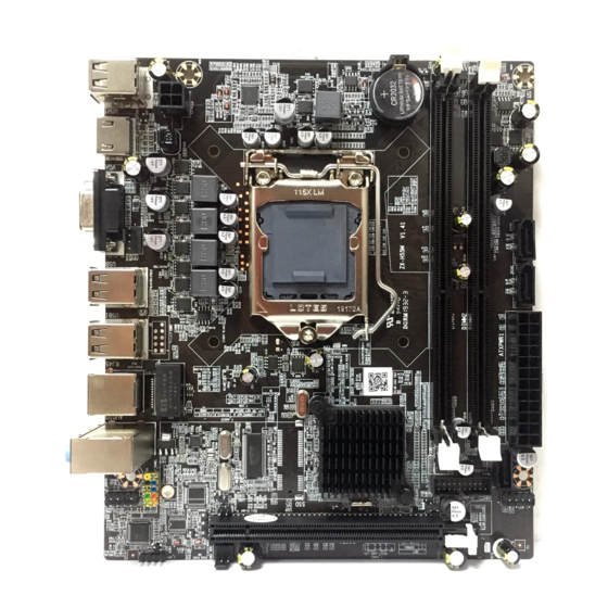
Page 7: Layout Diagram
USB Connectors CPU Socket RJ-45 Over Gigabit LAN Chip USB Connectors Audio Connector PCI Express2.0x16 by 16lane slot SYSFAN1 Intel H55 Chipset Realtek ALC662 Audio Decode HDMI-SPDIF PCI Express 2.0x1 slots Serial-ATAII Connector Header (SATA 1, 2, 3, 4) JBAT... -
Page 8: Chapter 2 Hardware Installation
Chapter 2 Hardware Installation Turn off your power when adding or removing expansion cards or WARNING! other system components. Failure to do so may cause severe damage to both your motherboard and expansion cards. 2-1 CPU Installation This motherboard provides an 1156-pin DIP, LGA 1156 Land Grid Array socket, referred to as the LGA 1156 socket. -
Page 9: Memory Module Installation
Memory Module Installation This motherboard provides two 240-pin DDR III DUAL INLINE MEMORY MODULES (DIMM) socket for DDR III memory expansion available to maximum memory volume of 8 GB DDRIII SDRAM. Valid Memory Configurations Bank 240-Pin DIMM Maximum Capacity DIMM1 DDR III 1066/ DDR III1333 DIMM2 DDR III 1066/ DDR III1333... -
Page 10: Expansion Slots
2-3 PCI Express Slots The H55 Express chipset based motherboard series offer one PCI-Express2.0 x16 graphics slots. Two PCI Express 2.0 x1 I/O slot and one 32-bit PCI slot guarantee the rich connectivity for the I/O of peripherals. PCI-E2.0 x1 slot PCI-E2.0 x16@16 Lane Slot... - Page 11 ROW1 ROW2 ROW1 ROW2 ROW1 ROW2 3.3V 3.3V 3.3V -12V Soft Power On Power OK +5V (for Soft Logic) +12V +12V Pin 1 Pin 1 24-Pin 20-Pin ** If you are using a 20-pin power plug, please refer to Figure1 for power supply connection.
- Page 12 (3) PS/2 Mouse & PS/2 Keyboard Connector: KB1 The connectors are for PS/2 keyboard and PS/2 Mouse. (4) USB Port connector: USB port fromUL1, USB1 The connectors are 4-pin connectors that connect USB devices with the 480 Mbit / sec data transfer rate to the system board. (5) LAN Port connector: RJ-45 LAN ports from UL1 This connector is standard RJ45 over USB connectors for Network connection.
-
Page 13: Headers
3-2 Headers (1) Line-Out/MIC Header for Front Panel (9-pin): FP_AUDIO1 These headers connect to Front Panel Line-out, MIC connector with cable. AU D I O P in 1 L ine-O ut, MIC Headers (2) USB Port Headers (9-pin): USB3/USB4 These headers are used for connecting the additional USB port plugs. By attaching an option USB cable, your can be provided with two additional USB plugs affixed to the back panel. - Page 14 PWRLED Pin 1 JW FP SPEAK Pin 1 Pin 1 System Case Connections (8) FAN Headers: SYSFAN1, (3-pin), CPUFAN1 (4-pin) These connectors support cooling fans of 350mA (4.2 Watts) or less, depending on the fan manufacturer, the wire and plug may be different. The red wire should be positive, while the black should be ground.
-
Page 15: Jumper Setting
HDMI_SPDIF_OUT HDMI_SPDIF Header 3-3 Jumper Setting (1) CMOS RAM Clear (2-pin): JBAT A battery must be used to retain the motherboard configuration in CMOS RAM, short 1-2 pins of JBAT to clear the CMOS data. To clear the CMOS, follow the procedure below: Turn off the system and unplug the AC power Remove ATX power cable from ATX power connector Locate JBAT and short pins 1-2 for a few seconds, if shorted with the jump cap,... -
Page 16: Chapter 4 Useful Help
Chapter 4 Useful Help 4-1 How to Update BIOS Step1. Prepare a bootable disk. (You may make one by click START click RUN type SYS A: click OK) Step2. Download upgrade tools and the latest BIOS files of the motherboard from official website and then make a copy of it to your bootable floppy disk after decompressing these files Step3.
Need help?
Do you have a question about the H55 and is the answer not in the manual?
Questions and answers