Intel DN2800MT Product Manual
Product guide for intel desktop board dn2800mt
Hide thumbs
Also See for DN2800MT:
- Specification (107 pages) ,
- Technical product specification (109 pages) ,
- Product manual (62 pages)
Table of Contents
Advertisement
Advertisement
Table of Contents

Related Manuals for Intel DN2800MT


Summary of Contents for Intel DN2800MT
- Page 1 Intel® Desktop Board DN2800MT Product Guide Order Number: G37706-002...
-
Page 2: Revision History
Intel may make changes to specifications and product descriptions at any time, without notice. Intel Desktop Board DN2800MT may contain design defects or errors known as errata which may cause the product to deviate from published specifications. Current characterized errata are available on request. -
Page 3: Intended Audience
The suitability of this product for other PC or embedded non-PC applications or other environments, such as medical, industrial, alarm systems, test equipment, etc. may not be supported without further evaluation by Intel. Document Organization The chapters in this Product Guide are arranged as follows:... - Page 4 Intel Desktop Board DN2800MT Product Guide Terminology The table below gives descriptions of some common terms used in the product guide. Term Description Gigabyte (1,073,741,824 bytes) Gigahertz (one billion hertz) Kilobyte (1024 bytes) Megabyte (1,048,576 bytes) Megabit (1,048,576 bits) Megahertz (one million hertz)
-
Page 5: Table Of Contents
Clearing Passwords....................38 Replacing the Battery ..................39 3 Updating the BIOS ® Updating the BIOS with the Intel Express BIOS Update Utility ......... 45 Updating the BIOS Using the F7 Function Key ............46 ® Updating the BIOS with the Intel Flash Memory Update Utility ........ - Page 6 8. Installing a PCI Express Mini Card in the Full-/Half-Mini Card Slot ......25 9. Installing a PCI Express Mini Card in the Half-Mini Card Slot ....... 26 10. Installing an Intel Z-U130 USB Solid-State Drive (or Compatible Device) ....28 11. Internal Headers and Connectors ..............29 12.
- Page 7 1. Intel Desktop Board DN2800MT Features ............9 2. Intel Desktop Board DN2800MT Components (Shown in Figure 1) ....... 13 3. Intel Desktop Board DN2800MT Components (Bottom) (Shown in Figure 2) ..14 4. S/PDIF Header Signal Names ................30 5.
- Page 8 Intel Desktop Board DN2800MT Product Guide viii...
-
Page 9: Desktop Board Features
1 Desktop Board Features ® This chapter briefly describes the features of Intel Desktop Board DN2800MT. Table 1 summarizes the major features of the Desktop Board. ® For a detailed description of Intel Desktop Board DN2800MT, refer to the Technical Product Specification at http://www.intel.com/Products/Desktop/Motherboards/db-... - Page 10 ― DMIC digital microphone input (internal header) ― Analog line-in (back panel jack) ― Front panel Intel HD Audio/AC’97 headphones/mic support (internal header) • 8-channel (7.1) Intel HD Audio via the HDMI interface Expansion • One PCI Express 1.0a x1 add-in card connector Capabilities •...
-
Page 11: Supported Operating Systems
• Thermal sense to detect out of range thermal values • One 3-pin system fan header with speed control • Support for Platform Environmental Control Interface (PECI) Supported Operating Systems For the latest information on operating system support refer to the Intel Desktop Board DN2800MT web page at http://www.intel.com/products/motherboard/index.htm. -
Page 12: Desktop Board Components
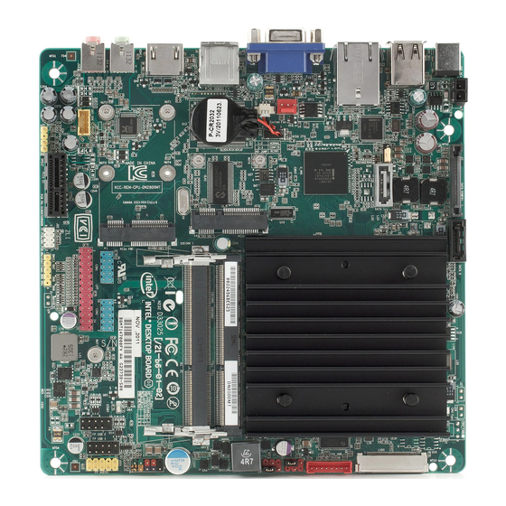
Intel Desktop Board DN2800MT Product Guide Desktop Board Components Figure 1 shows the approximate location of the major components on the top side of Intel Desktop Board DN2800MT. Figure 1. Intel Desktop Board DN2800MT Components (Top) -
Page 13: Intel Desktop Board Dn2800Mt Components (Shown In Figure 1)
Desktop Board Features Table 2. Intel Desktop Board DN2800MT Components (Shown in Figure 1) Label Description Battery Back panel connectors System fan header Internal DC power connector Intel NM10 Express Chipset BIOS configuration jumper block SATA 3.0 Gb/s Port 1 connector... -
Page 14: Intel Desktop Board Dn2800Mt Components (Bottom)
Table 3. Intel Desktop Board DN2800MT Components (Bottom) (Shown in Figure 2) Label Description eDP connector Online Support For more information on Intel Desktop Board DN2800MT, consult the following online resources: • Intel Desktop Board DN2800MT http://www.intel.com/products/desktop/motherboard/ index.htm • Desktop Board Support http://www.intel.com/p/en_US/support?iid=hdr+supp... -
Page 15: Installing And Replacing Desktop Board Components
Install and remove system memory • Connect to SATA drives Install a PCI Express Mini Card • Install an Intel Z-U130 USB Solid-State Drive or Compatible Device • Connect to the internal headers and connectors • Connect a system fan •... -
Page 16: Installation Precautions
Intel Desktop Board DN2800MT Product Guide Installation Precautions When you install and test the Intel Desktop Board, observe all warnings and cautions in the installation instructions. To avoid injury, be careful of: • Sharp pins on connectors Sharp pins on printed circuit assemblies •... -
Page 17: Installing The I/O Shield
Installing and Replacing Desktop Board Components Installing the I/O Shield This Desktop Board comes with I/O shields. When installed in the chassis, the shield blocks radio frequency transmissions, protects internal components from dust and foreign objects, and promotes correct airflow within the chassis. Select the proper I/O shield for the chassis you have chosen to use. -
Page 18: Installing And Removing The Desktop Board
Refer to your chassis manual for instructions on installing and removing the Desktop Board. Figure 4 shows the location of the mounting screw holes for Intel Desktop Board DN2800MT. Figure 4. Intel Desktop Board DN2800MT Mounting Screw Hole Locations... -
Page 19: Installing System Memory
Installing System Memory NOTE To be fully compliant with all applicable Intel SDRAM memory specifications, the board requires SO-DIMMs that support the Serial Presence Detect (SPD) data structure. The desktop board has two 204-pin DDR3 SO-DIMM sockets supporting two memory modules on a single channel. -
Page 20: Installing An So-Dimm
Intel Desktop Board DN2800MT Product Guide Figure 5. Installing an SO-DIMM... -
Page 21: Removing An So-Dimm
Installing and Replacing Desktop Board Components To remove an SO-DIMM from the socket, gently spread the socket’s retention arms as shown in Figure 6 to disengage them from the SO-DIMM. Figure 6. Removing an SO-DIMM... -
Page 22: Connecting To Sata Drives
Intel Desktop Board DN2800MT Product Guide Connecting to SATA Drives Intel Desktop Board DN2800MT supports two SATA drives with two data connectors and one power connector. To enable low-profile connectivity, the board ships with two SATA data cables with right-angled connectors and an in-line power cable that provides: •... -
Page 23: Connecting The Sata Data And Power Cables
Installing and Replacing Desktop Board Components Figure 7. Connecting the SATA Data and Power Cables... -
Page 24: Installing A Pci Express Mini Card In The Pci Express Full-/Half-Mini Card Slot
Intel Desktop Board DN2800MT Product Guide Installing a PCI Express Mini Card in the PCI Express Full-/Half-Mini Card Slot A PCI Express Full-Mini or Half-Mini Card can be installed in the Desktop Board’s PCI Express Full-/Half-Mini Card slot. To install a PCI Express Full-Mini Card in this slot, see Figure 8 and follow these steps: 1. -
Page 25: Installing A Pci Express Mini Card In The Full-/Half-Mini Card Slot
Installing and Replacing Desktop Board Components Figure 8. Installing a PCI Express Mini Card in the Full-/Half-Mini Card Slot... -
Page 26: Installing A Pci Express Mini Card In The Pci Express Half-Mini Card Slot
Intel Desktop Board DN2800MT Product Guide Installing a PCI Express Mini Card in the PCI Express Half-Mini Card Slot A PCI Express Half-Mini Card can be installed in the Desktop Board’s PCI Express Half-Mini Card slot. To install a PCI Express card in this slot, see Figure 9 and follow these steps: 1. -
Page 27: Installing An Intel ® Z-U130 Usb Solid-State Drive Or Compatible Device
Z-U130 USB Solid-State Drive or Compatible Device An Intel Z-U130 USB Solid-State Drive or compatible device can be installed on the Desktop Board by using the onboard USB 2.0 header shown in Figure 1, U. This header provides support for the solid-state drive. -
Page 28: Installing An Intel Z-U130 Usb Solid-State Drive (Or Compatible Device)
Intel Desktop Board DN2800MT Product Guide Figure 10. Installing an Intel Z-U130 USB Solid-State Drive (or Compatible Device) -
Page 29: Connecting To The Internal Headers And Connectors
Before connecting cables to any of the internal headers and connectors, observe the precautions in “Before You Begin” on page 15. Figure 11 shows the location of the internal headers and connectors on Intel Desktop Board DN2800MT. Figure 11. Internal Headers and Connectors... -
Page 30: S/Pdif Header
Intel Desktop Board DN2800MT Product Guide S/PDIF Header Figure 11, A shows the location of the S/PDIF output header. Table 13 shows the pin assignments and signal names for the S/PDIF output header. Table 4. S/PDIF Header Signal Names Description... -
Page 31: Parallel Port Header
Installing and Replacing Desktop Board Components Parallel Port Header Figure 11, D shows the location of the parallel port header. Table 7 shows the pin assignments and signal names for the parallel port header. Table 7. Parallel Port Header Signal Name Signal Name STROBE# AUTOFD#... -
Page 32: Front Panel Audio Header
Intel Desktop Board DN2800MT Product Guide Front Panel Audio Header The front panel audio header shown in Figure 11, F supports both Intel HD Audio and AC ’97 Audio. Table 9 shows the pin assignments and signal names for Intel HD Audio and Table 10 shows the pin assignments and signal names for AC ’97 Audio. -
Page 33: Front Panel Usb 2.0 Header (With Flash Drive Support)
Installing and Replacing Desktop Board Components Front Panel USB 2.0 Header (with Flash Drive Support) Figure 11, H shows the location of the standard front panel dual-port USB 2.0 header and Table 12 shows the pin assignments and signal names. Table 12. -
Page 34: Custom Solutions Header
Intel Desktop Board DN2800MT Product Guide Custom Solutions Header Figure 11, J shows the location of the Custom Solutions header and Table 14 shows the pin assignments and signal names. Table 14. Custom Solutions Header Signal Names Signal Name Signal Name... -
Page 35: Connecting To A Power Supply
10 A. Use of an external power supply is preferred. Total power consumption depends on the system configuration selected by the integrator. Refer to the Intel Desktop Board DN2800MT Technical Product Specification for further guidance. Figure 13. Power Supply Connections... - Page 36 Intel Desktop Board DN2800MT Product Guide CAUTION The external power jack is the primary power input connector of Intel Desktop Board DN2800MT. However, the Desktop Board also provides an internal 1 x 2 power connector that can used be with a target system that already has an internal power supply.
-
Page 37: Setting The Bios Configuration Jumper
Installing and Replacing Desktop Board Components Setting the BIOS Configuration Jumper NOTE Always turn off the power and unplug the power cord from the computer before moving the jumper. Moving the jumper with the power on may result in unreliable computer operation. -
Page 38: Clearing Passwords
Intel Desktop Board DN2800MT Product Guide The three-pin BIOS jumper block enables board configuration to be done in the BIOS Setup program. Table 15 shows the jumper settings for the BIOS Setup program modes. Table 15. Jumper Settings for the BIOS Setup Program Modes... -
Page 39: Replacing The Battery
Installing and Replacing Desktop Board Components Replacing the Battery A coin-cell battery (CR2032) powers the real-time clock and CMOS memory. When the computer is not plugged into a wall socket, the battery has an estimated life of three years. When the computer is plugged in, the standby current from the power supply extends the life of the battery. - Page 40 Intel Desktop Board DN2800MT Product Guide VORSICHT Bei falschem Einsetzen einer neuen Batterie besteht Explosionsgefahr. Die Batterie darf nur durch denselben oder einen entsprechenden, vom Hersteller empfohlenen Batterietyp ersetzt werden. Entsorgen Sie verbrauchte Batterien den Anweisungen des Herstellers entsprechend. AVVERTIMENTO Esiste il pericolo di un esplosione se la pila non viene sostituita in modo corretto.
- Page 41 Installing and Replacing Desktop Board Components Προσοχή Υπάρχει κίνδυνος για έκρηξη σε περίπτωση που η μπαταρία αντικατασταθεί από μία λανθασμένου τύπου. Οι μπαταρίες θα πρέπει να ανακυκλώνονται όταν κάτι τέτοιο είναι δυνατό. Η απόρριψη των χρησιμοποιημένων μπαταριών πρέπει να γίνεται σύμφωνα με τους...
- Page 42 Intel Desktop Board DN2800MT Product Guide UPOZORNENIE Ak batériu vymeníte za nesprávny typ, hrozí nebezpečenstvo jej výbuchu. Batérie by sa mali podľa možnosti vždy recyklovať. Likvidácia použitých batérií sa musí vykonávať v súlade s miestnymi predpismi na ochranu životného prostredia.
- Page 43 Installing and Replacing Desktop Board Components To replace the battery, follow these steps: 1. Observe the precautions in "Before You Begin" (see page 15). 2. Turn off all peripheral devices connected to the computer. Disconnect the computer’s power cord from the AC power source (wall outlet or power adapter). 3.
-
Page 44: Removing And Replacing The Battery
Intel Desktop Board DN2800MT Product Guide Figure 15. Removing and Replacing the Battery... -
Page 45: Updating The Bios
Power-On Self-Test (POST) memory test begins and before the operating system boot begins. This chapter tells you how to update the BIOS by either using the Intel Express BIOS Update utility or the Intel Flash Memory Update Utility, and how to recover the BIOS ®... -
Page 46: Updating The Bios Using The F7 Function Key
BIOS from a bootable CD-ROM, bootable USB flash drive, or other bootable USB media. You can update to a new version of the BIOS by using the Intel Flash Memory BIOS update file. The Intel Flash Memory BIOS update file is a compressed file that contains the files you need to update the BIOS. -
Page 47: Recovering The Bios
You can obtain the Recovery BIOS Update file through your computer supplier or by navigating to the Intel Desktop Board DN2800MT page on the Intel World Wide Web site Download Center at http://downloadcenter.intel.com. On the DN2800MT page, click on the “BIOS Update” link and then select the Recovery BIOS Update file. NOTE... - Page 48 Intel Desktop Board DN2800MT Product Guide...
-
Page 49: A Error Messages And Indicators
A Error Messages and Indicators This appendix describes error messages generated by the Desktop Board’s BIOS. The BIOS indicates these error messages with LED blink codes, speaker beep codes, and by text displayed on the PC monitor. Front-panel Power LED Blink and Speaker Beep Codes Whenever a recoverable error occurs during POST, the BIOS provides basic status and error messages through front-panel power LED blink codes (Table 16) as well as... -
Page 50: Bios Error Messages
Intel Desktop Board DN2800MT Product Guide Table 17. BIOS Speaker Beep Codes Type Pattern Frequency/Comments Video error On-off (1.0 second each) two times, then a 932 Hz 2.5-second pause (off), the entire pattern repeats (beeps and pause) once and the BIOS will continue to boot. -
Page 51: B Regulatory Compliance
Product Ecology statements Electromagnetic Compatibility (EMC) regulations • Product certifications • Safety Standards Intel Desktop Board DN2800MT complies with the safety standards stated in Table 19 when correctly installed in a compatible host system. Table 19. Safety Standards Regulation Title CSA/UL 60950-1 Information Technology Equipment –... -
Page 52: European Union Declaration Of Conformity Statement
Intel Desktop Board DN2800MT Product Guide European Union Declaration of Conformity Statement We, Intel Corporation, declare under our sole responsibility that the product Intel ® Desktop Board DN2800MT is in conformity with all applicable essential requirements necessary for CE marking, following the provisions of the European Council Directives 2004/108/EC (EMC Directive), 2006/95/EC (Low Voltage Directive), and 2002/95/EC (ROHS Directive). -
Page 53: Product Ecology Statements
The following information is provided to address worldwide product ecology concerns and regulations. Recycling Considerations As part of its commitment to environmental responsibility, Intel has implemented the ® Intel Product Recycling Program to allow retail consumers of Intel’s branded products to return used products to selected locations for proper recycling. - Page 54 Français Dans le cadre de son engagement pour la protection de l'environnement, Intel a mis en œuvre le programme Intel Product Recycling Program (Programme de recyclage des produits Intel) pour permettre aux consommateurs de produits Intel de recycler les produits usés en les retournant à...
- Page 55 Regulatory Compliance Portuguese Como parte deste compromisso com o respeito ao ambiente, a Intel implementou o Programa de Reciclagem de Produtos para que os consumidores finais possam enviar produtos Intel usados para locais selecionados, onde esses produtos são reciclados de maneira adequada.
-
Page 56: China Rohs
The China Ministry of Information Industry (MII) stipulates that a material Self Declaration Table (SDT) must be included in a product’s user documentation. The SDT for Intel Desktop Board DN2800MT is shown in Figure 16. Figure 16. Intel Desktop Board DN2800MT China RoHS Material... -
Page 57: Emc Regulations
Regulatory Compliance EMC Regulations Intel Desktop Board DN2800MT complies with the EMC regulations stated in Table 20 when correctly installed in a compatible host system. Table 20. EMC Regulations Regulation Title FCC 47 CFR Part 15, Title 47 of the Code of Federal Regulations, Part 15, Subpart B, Subpart B Radio Frequency Devices. -
Page 58: Canadian Department Of Communications Compliance Statement
Consult the dealer or an experienced radio/TV technician for help. • Any changes or modifications to the equipment not expressly approved by Intel Corporation could void the user’s authority to operate the equipment. Tested to comply with FCC standards for home or office use. -
Page 59: Korea Class B Statement
Regulatory Compliance Korea Class B Statement Korea Class B Statement translation: This equipment is for home use, and has acquired electromagnetic conformity registration, so it can be used not only in residential areas, but also other areas. Ensure Electromagnetic Compatibility (EMC) Compliance Before computer integration, make sure that the power supply and other modules or peripherals, as applicable, have passed Class B EMC testing and are marked... -
Page 60: Product Certifications
Intel Desktop Board DN2800MT Product Guide Product Certifications Board-Level Certifications Intel Desktop Board DN2800MT has the regulatory compliance marks shown in Table 21. Table 21. Regulatory Compliance Marks Description Mark UL joint US/Canada Recognized Component mark. Includes adjacent UL file number for Intel Desktop Boards: E210882. -
Page 61: Chassis- And Component-Level Certifications
Compliance The US Department of Energy and the US Environmental Protection Agency have continually revised the ENERGY STAR requirements. Intel has worked directly with these two governmental agencies in the definition of the new requirements. This Desktop Board meets the ENERGY STAR Program for Computers: Version 5.0 Category A requirements. - Page 62 Intel Desktop Board DN2800MT Product Guide...
Need help?
Do you have a question about the DN2800MT and is the answer not in the manual?
Questions and answers