Table of Contents
Advertisement
Quick Links
USER'S MANUAL
Of
Intel Z68 Express Chipset
Based
M/B for Intel LGA 1155 Processors
NO. G03-TIZ68MG-L-F
Rev: 1.0
Release date: September, 2011
Trademark:
* Specifications and Information contained in this documentation are furnished for information use only, and are
subject to change at any time without notice, and should not be construed as a commitment by manufacturer.
Advertisement
Table of Contents

Subscribe to Our Youtube Channel
Related Manuals for Intel Z68


Summary of Contents for Intel Z68
- Page 1 USER'S MANUAL Intel Z68 Express Chipset Based M/B for Intel LGA 1155 Processors NO. G03-TIZ68MG-L-F Rev: 1.0 Release date: September, 2011 Trademark: * Specifications and Information contained in this documentation are furnished for information use only, and are subject to change at any time without notice, and should not be construed as a commitment by manufacturer.
- Page 2 Environmental Safety Instruction Avoid the dusty, humidity and temperature extremes. Do not place the product in any area where it may become wet. 0 to 40 centigrade is the suitable temperature. (The figure comes from the request of the main chipset) Generally speaking, dramatic changes in temperature may lead to contact malfunction and crackles due to constant thermal expansion and contraction from the welding spots’...
-
Page 3: Table Of Contents
TABLE OF CONTENT CHAPTER 1 INTRODUCTION OF INTEL Z68 MOTHERBOARDS......1 1-1 FEATURES OF MOTHERBOARD..............1 1-1-1 SPECIAL FEATURES OF MOTHERBOARD..........1 1-2 SPECIFICATION ....................2 1-3 LAYOUT DIAGRAM....................3 CHAPTER 2 HARDWARE INSTALLATION ............5 2-1 CPU INSTALLATION ..................5 2-2 MEMORY MODULE INSTALLATION..............6 2-3 EXPASION CARD INSTALLATION ..............7 2-3-1 EXPASION SLOTS..................7... -
Page 4: Chapter 1 Introduction Of Intel Z68 Motherboards
Introduction of Intel Z68 Motherboards Features of Motherboard The Intel Z68 Express chipset based motherboard series are based on Intel Z68 Express chipset technology which supports the innovative Intel LGA 1155 socket Intel® Core™ i7, Intel® Core™ i5, Core™ i3 Processor. -
Page 5: Specification
Description Design U-ATX; PCB size:24.5cmx18.0cm Chipset Intel Z68 Express Chipset ® supports the innovative Intel LGA 1155 socket Intel CPU Socket Core™ i7, Core™ i5, Core™ i3 Processor DDRIII module slot x 2 Support 2pcs DDRIII 1066/1333/1600/1866 memory Memory Slot... -
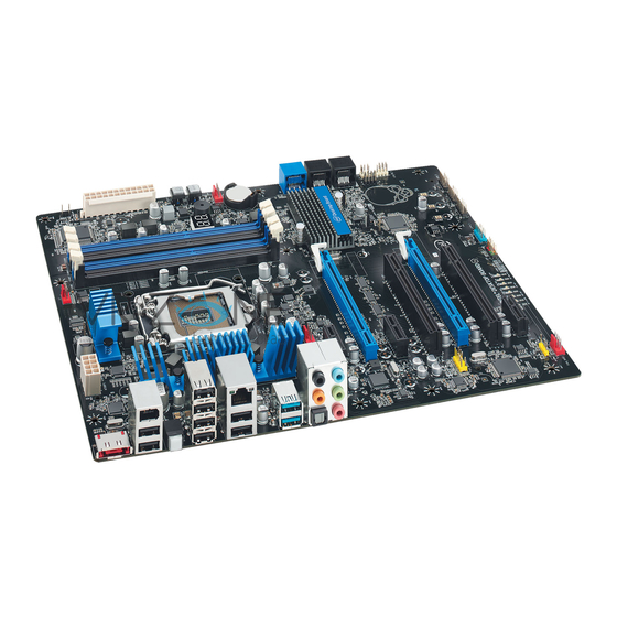
Page 6: Layout Diagram
Gigabit LAN Chip SATAIII Ports (SATA 1 & SATA2) PCI Express 2.0x1 slots JBAT SATAII Ports (SATA3 & SATA4) Intel Z68 Chipset 6-CH HD Audio Chip HDMI-SPDIF Header Power LED Header Speaker Header Front Panel Audio Header COM Header Front Panel Header... - Page 7 SYSFAN1 Header Gigabit LAN Chip SATAIII Ports (SATA 1 & SATA2) PCI Express 2.0x1 slots JBAT SATAII Ports 6-CH HD Audio Chip Intel Z68 Chipset (SATA3 & SATA4) HDMI-SPDIF Header Power LED Header Speaker Header Front Panel Audio Header COM Header...
-
Page 8: Chapter 2 Hardware Installation
Chapter 2 Hardware Installation Turn off your power when adding or removing expansion cards or WARNING! other system components. Failure to do so may cause severe damage to both your motherboard and expansion cards. 2-1 CPU Installation This motherboard provides an 1155-pin DIP, LGA 1155 Land Grid Array socket, referred to as the LGA 1155 socket. -
Page 9: Memory Module Installation
Memory Module Installation This motherboard provides two 240-pin DDR III DUAL INLINE MEMORY MODULES (DIMM) socket for DDR III memory expansion available to maximum memory volume of 8 GB DDRIII SDRAM. Valid Memory Configurations Bank 240-Pin DIMM Maximum Capacity DIMM1 DDR III 1066/ 1333/1600/1866 DIMM2 DDR III 1066/ 1333/1600/1866... -
Page 10: Expasion Card Installation
2-3 Expansion Slots 2-3-1 Expansion Slot The Z68 Express chipset based motherboard series offer one PCI-Express 2.0 x16 graphics slot and two PCI Express 2.0 x1 I/O slots to guarantee the rich connectivity for the I/O of peripherals. PCI-E2.0 x16@16 Lane Slot PCI-E 2.0 x1 slot... -
Page 11: Chapter 3 Connctors, Headers & Jumpers Setting
Chapter 3 Connectors, Headers &Jumper Setting 3-1 Motherboard Internal Connectors (1) Power Connector (24-pin block): ATXPWR1 ATX Power Supply connector: This is a new defined 24-pins connector that usually comes with ATX case. The ATX Power Supply allows using soft power on momentary switch that connect from the front panel switch to 2-pins Power On jumper pole on the motherboard. - Page 12 (2) ATX 12V Power Connector (8-pin block) : ATX12V1 This is a new defined 8-pin connector that usually comes with ATX Power Supply. The ATX Power Supply which fully supports LGA 1155 processor must including this connector for support extra 12V voltage to maintain system power consumption.
-
Page 13: I/O Back Panel Connectors
3-2 I/O Back Panel Connectors USB 2.0 Ports RJ-45 LAN Port Optional Line-IN USB 3.0 DVI Port VGA Port Ports Line-OUT MIC-IN USB 2.0 Ports Coaxial PS/2 Keyboard Port SPDIF_OUT Port * Note: The above diagram is for illustration purpose only. USB3.0 ports are only optional for TIZ68MG3-L model. -
Page 14: Headers
3-3 Headers (1) Line-Out/MIC Header for Front Panel (9-pin): FP_AUDIO These headers connect to Front Panel Line-out, MIC connector with cable. AU D I O P in 1 L ine-O ut, MIC Headers (2) USB Port Headers (9-pin): USB1/USB2 These headers are used for connecting the additional USB port plugs. By attaching an option USB cable, your can be provided with two additional USB plugs affixed to the back panel. - Page 15 PWRLED Pin 1 JW FP SPEAK Pin 1 Pin 1 System Case Connections (8) FAN Headers: SYSFAN1 (3-pin), CPUFAN1 (4-pin) These connectors support cooling fans of 350mA (4.2 Watts) or less, depending on the fan manufacturer, the wire and plug may be different. The red wire should be positive, while the black should be ground.
- Page 16 HDMI_SPDIF_OUT HDMI_SPDIF Header (11) LPC_CON header: LPC_CON Pin 1 LPC_CON...
-
Page 17: Jumper Setting
3-4 Jumper Setting (1) KB/MS Power on Function Enabled/Disabled: JP1 1-2 Closed: KB/MS Power ON Disable (Default) 2-3 Closed: KB/MS Power ON Enabled Keyboard /Mouse Power On Setting (2) CMOS RAM Clear (3-pin): JBAT A battery must be used to retain the motherboard configuration in CMOS RAM. Note: When should clear CMOS Troubleshooting Forget password... -
Page 18: Chapter 4 Useful Help
Chapter 4 Useful Help 4-1 How to Update BIOS Solution1: Updating BIOS under DOS: 1. Prepare a bootable disk. (You may make one by click START click RUN type SYS click OK) 2. Download upgrade tools and the latest BIOS files of the motherboard from official website and then make a copy of it to your bootable floppy disk after decompressing these files 3. -
Page 19: Appendix
Appendix Thunder Protection Feature Introduction: Thunder is such formidable natural force that it can render massive damage to electronic products of all kinds. In thunderstorm season computer systems without powerful thunder protection designs are vulnerable to electric surge damage. High-priced building with thunder protection measures may be a good choice, but usually costly and with corners uncovered. - Page 20 Conclusion: Jetway’s Thunder Series motherboard can guard motherboard from thunder electric surge damage with effect and ensure system security from as high as 9KV volts of electric surge. Bonus of Thunder-protection Motherboard Jetway Thunder series motherboards adopt dual thunder protection walls to cover every corner in network loops.
Need help?
Do you have a question about the Z68 and is the answer not in the manual?
Questions and answers