
Related Manuals for TELECO AUTOMATION TVNRG868A01


Summary of Contents for TELECO AUTOMATION TVNRG868A01
- Page 1 Control system for garage doors Installer’s instruction manual Product: TVNRG868A01 Doc: TEMP Date: 07/09/2018...
- Page 2 INDEX 1. PRODUCT DESCRIPTION --------------------------------------------------------------- p. 3 2. INSTALLATION ----------------------------------------------------------------------- p. 4 - 8 2.1 Mounting the product 2.2 Mounting the wireless safety system (BST24/BST25/BST25S) 2.3 Control unit diagram 2.4 Electrical connections 2.5 Wired safety device connections 3. PRELIMINARY CHECK AND INITIAL START-UP --------------------------------------- p.
-
Page 3: Product Description
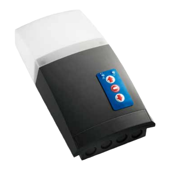
1. PRODUCT DESCRIPTION TVNRG868A01 Control unit with integrated radio receiver for the remote control of tubular motors up to 450W, with built-in limit switch, for rolling shutters and rolling doors. FEATURES Plastic case with easy fixing Front cover with up/stop/down buttons... -
Page 4: Basic Installation
2. INSTALLATION Basic installation 1 - NRG control unit 2 - Tubular motor (240Vac) 3 - Hand transmitter 4 - Safety edge wireless transmitter Complete installation 1 - NRG control unit 2 - Tubular motor (240Vac) 3 - Hand transmitter 4 - Safety edge wireless transmitter 5 - Alarm wireless sensor 6 - Wireless security keypad... -
Page 5: Mounting The Product
2.1 MOUNTING THE PRODUCT OPENING THE COVER BOX DIMENSIONS 80 mm 290 mm MOUNTING SIDE 85 mm 145 mm 95 mm... - Page 6 2.2 MOUNTING THE WIRELESS SAFETY SYSTEM (BST24/BST25/BST25S) The system is composed by a radio card (MASTER), plugged in the control unit, and a wireless transmitter (SLAVE) mounted on the door, usually close to the bottom slat, connected to the safety device. The device has got infrared low-consumption barrier (both safety systems) or 8,2KOhm resistive barrier safety edge (only for BST24/BST25).
-
Page 7: Control Unit Diagram
2.3 CONTROL UNIT DIAGRAM 1 - High voltage terminals Via dell'Artigianato, 16 - 31014 Colle Umberto (TV) ITALY Via dell'Artigianato, 16 - 31014 Colle Umberto (TV) ITALY 2 - Low voltage terminals Tel. +39.0438.388511 Fax +39.0438.388536 Tel. +39.0438.388511 Fax +39.0438.388536 3 - 3.15A fuse Web site: www.telecoautomation.com Web site: www.telecoautomation.com... - Page 8 2.5 WIRED SAFETY DEVICE CONNECTIONS Infrared (IR) safety edge 8.2Kohm resistive safety edge 12 13 14 15 16 17 18 19 20 21 22 23 12 13 14 15 16 17 18 19 20 21 22 23 12 13 14 15 16 17 18 19 20 21 22 23 12 13 14 15 16 17 18 19 20 21 22 23 16- BROWN RX FTC010...
- Page 9 3. PRELIMINARY CHECK AND INITIAL START-UP • Step 1: motor limit switch setting A proper connection box should be used to set the limit switch before wiring the motor in the control unit or follow the procedure described on par. 3.1. •...
- Page 10 3.1 Limit switches configuration Factory setting: ACTIVATED Procedure only with hold to run commands. The safety devices are excluded! Warning: ACTIVATION keep pressed Press together P1 and P2 and keep them pressed for 3s. The buzzer makes one beep. Open the door (in hold-to-run mode) in order to set up the upper limit switch.
- Page 11 3.3 Exclusion of safety edge in the last 5 cm of the closure In case of uneven floors, it could be necessary deactivating the safety edge in the last part of the closure (not more than 5 cm to comply with the standards) in order to avoid any accidental activation of the safety edge. This procedure must be performed by qualified installer only, who will take charge of its correct application.
- Page 12 4. Transmitter memorization This operation should be done using the button P1. Please refer to the schematic diagram on page 7 in order to localize the position on the board. OPEN - STOP - CLOSE ► 4.1 Single channel memorization Memorization of a single button of any transmitter, with function OPEN - STOP - CLOSE keep it pressed...
- Page 13 4.4 Four channels memorization OPEN ► Memorization of four button transmitter in one step. CLOSE ► STOP ► LIGHT ON - LIGHT OFF ► keep it pressed button to Press P1 six times and keep it pressed. memorize The buzzer emits a continuous sound. Press any button of the transmitter to memorize.
- Page 14 4.7 Alarm function: shock sensor memorization Only for TVSSH868A01 (with BST25S is not necessary the shock sensor memorization). The wireless shock sensor (optional) detects any attempt of breaking or entering and send a signal TVSSH868A01 to the control unit that will activate the speaker (optional) for 1 minute.
- Page 15 5. TRANSMITTERS DELETION This operation should be done using the button P2. Please refer to the schematic diagram on page 7 in order to localize the position on the board. 5.1 Deleting a single transmitter keep it pressed Press P2 four times and keep it pressed. button to delete The buzzer emits an intermittent sound.
- Page 16 6.1 Auto close time setting This procedure configures the time lapse between complete opening and the automatic closure (if enabled). The default time is 30 seconds. It is possible to set the time from 5 seconds to 180 seconds. memorized memorized memorized memorized...
- Page 17 7.1 Motor torque control This procedure activates or deactivates the motor torque control. The control unit will costantly check the level of current required by the motor during the movement in order to detect any anomaly in the normal operation of the door. In case of excessive effort, the control unit will stop and reverse the manoeuvre. DEACTIVATED memorized memorized...
-
Page 18: Technical Specifications
2 x 1.5V AA or 2 x 3.6V lithium batteries Consumption when transmitting 13mA The manufacturer, Teleco Automation s.r.l, declares that the type of radio equipment is compliant with Directive 2014/53/EU. The full text of the EU compliance declaration is available at the following Internet address: www.telecoautomation.com/ce. - Page 19 9. TROUBLESHOOTING (What to do if...) Acoustic signals from the control unit Sequence Meaning Solution 1 costant beep Faulty control unit Replace the control unit (continuous or intermittent) 2 beeps Motor problem - Set the limit switches - The thermal protection could be activated. Wait while the motor cools down.
-
Page 20: Other Possible Issues
5 seconds. The control unit will automatically switch to hold-to-run mode. Branches: Headquarters: Teleco Automation France - France Teleco Automation Srl - Italy info@telecofrance.com info@telecoautomation.com Teleco Automation GmbH - Germany info.de@telecoautomation.com Teleco Automation Oceania Pty Ltd - Australia telecoautomation.com info@telecoautomation.com.au...
Need help?
Do you have a question about the TVNRG868A01 and is the answer not in the manual?
Questions and answers
How to open the panel TVNRG868E02 to get to the reprogramming button. I’ve removed the two screws near the bottom.
To access the reprogramming button (P2) on the TELECO AUTOMATION TVNRG868A01, open the front cover of the plastic case. The front cover includes the up/stop/down buttons and provides access to internal components, including the reprogramming button. Refer to the schematic diagram on page 7 to locate button P2 on the board.
This answer is automatically generated
hi can you advise how i alter the settings for the garage door to go all the way up
To adjust the TELECO AUTOMATION TVNRG868A01 garage door settings so it goes all the way up, follow these steps:
1. Press and hold buttons P1 and P2 together for 3 seconds until the buzzer beeps once.
2. Open the door using hold-to-run mode to set the upper limit switch.
3. Close the door using hold-to-run mode to set the lower limit switch.
This procedure configures the limit switches, ensuring the door fully opens.
This answer is automatically generated