Table of Contents
Advertisement
RPA60/120/240
Public Address Mixer Amplifier with
Integrated BT/Tuner/Media Player
Product Featuresoduct
Features
• 70V/4ohm Compatible
• 4 Zone 70V Speaker Outputs
• 6 Input Audio Mixer with Bass/Treble
• Integrated BT/Tuner/Media Player
• 3 Microphone Inputs
• 2 Aux Inputs
• Fire Alarm/Emergency/Chime/Telephone Inputs
• Phantom Power
• 24V DC Battery Power Input
• 120V AC Power Input
WWW.RAVETECHNOLOGY.COM
Advertisement
Table of Contents

Related Manuals for Rave RPA60


Summary of Contents for Rave RPA60
- Page 1 RPA60/120/240 Public Address Mixer Amplifier with Integrated BT/Tuner/Media Player Product Featuresoduct Features • 70V/4ohm Compatible • 4 Zone 70V Speaker Outputs • 6 Input Audio Mixer with Bass/Treble • Integrated BT/Tuner/Media Player • 3 Microphone Inputs • 2 Aux Inputs •...
-
Page 2: Ground Connection
Precautions READ FOLLOWING INSTRUCTIONS FOR YOUR OWN SAFETY • ALWAYS KEEP THESE INSTRUCTIONS. DO NOT THROW THEM AWAY • NEVER EXPOSE THIS EQUIPMENT TO RAIN, MOISTURE, ANY DRIPPING OR SPLASHING LIQUID. AND NEVER PLACE AN OBJECT FILLED WITH LIQUID ON TOP OF THIS DEVICE. -
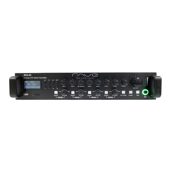
Page 3: Rear Panel Description
Rear panel description AC Power Connection: This connection is an IEC C14 power connector. Connect the included power cable from a 110-120V AC power outlet to the unit. A fuse holder with main fuse is located on the right of the AC power connector. When replacing the fuse, make sure the replacement matches the specifications of the original fuse. - Page 4 Loudspeaker output connections: Main speaker output connections for both low impedance and constant voltage distributed are on the 4-pin terminal block connector. The zone (1-4) 70V constant voltage outputs are on an 8-pin terminal block connector. More information about loudspeaker output connections is described in a further chapter of this instruction manual.
- Page 5 Unbalanced line inputs 2 & 3 (RCA jack): Line 2 and 3 stereo RCA inputs. Chime & Fire inputs (Terminal block): Chime & Fire inputs can be connected to any external source, such as call station, signal matrix, fire alarm system. The chime and fire outputs have priority over all other inputs.
-
Page 6: Front Panel Description
SD/MMC Front panel description Master volume control: Master volume control overall volume for all output channels. Input volume controls: Using the input level controls, the individual level for each connected input can be adjusted to the preferred level. Chime: When the chime button is pressed the chime tone as pre-announcement for paging will be played once. - Page 7 Zone 1-4 on/off button: The different speaker zone outputs (1-4) can be switched on and off by pressing the on/off button of the corresponding zone. When the zone (1-4) is enabled the on/off button will illuminate green to indicate the zone is on. When the ‘All’ button is pressed all zones will turn on or off.
-
Page 8: Setting Up The System
Setting up the system ATTENTION! Make sure the power of the device is turned OFF before any wiring connections or adjustments are made. 1) Connecting the Speakers The speakers connect to the 2 terminal blocks on the back panel of the device. This device is compatible with low impedance and constant voltage speakers depending on the projects requirements. - Page 9 matching matching transformer transformer matching matching transformer transformer matching transformer Example diagram constant voltage connections 2) Connecting the audio sources The next step is adding source input connections. Depending of the type, connect the output of the audio source to the corresponding input channel. Before connecting, turn all the channel gain and master volume controls on the front and rear panel of the amplifier to their minimum setting.
- Page 10 3) Phantom power MIC input 1 & 2 inputs have phantom power for powering condenser microphones. Enabling of the phantom power can be done by the switches located between MIC 1 & 2 connections. Switch 2 will enable phantom power to input 1, while switch 1 enables phantom power to input 2.
-
Page 11: Pin Connections And Connectors
Pin connections and connectors CONNECTION STANDARDS The input and output connections correspond to international wiring standards for professional audio equipment. RCA (Cinch): For unbalanced line input connections. Signal Ground Tip: Sleeve: Left Right White: Red: XLR: For balanced signal input connections Ground Pin 1: Signal +... -
Page 12: System Block Diagram
System Block diagram... -
Page 13: Technical Specifications
Ante nna input MHz 7 5 Ω unbalanc e d Outputs Low Impe danc e 4Ω Cons tant V oltage Impe danc e 167Ω - RPA60 84Ω - RPA120 42Ω - RPA240 Indic ators Powe r /Zone /Output Playe r... - Page 14 5-Year Limited Warranty Rave Technology products are warranted to be free from defects in workmanship and materials for a period of Five (5) years from the date of purchase without charge for parts or labor. This warranty does not apply to units that have been subject to...
Need help?
Do you have a question about the RPA60 and is the answer not in the manual?
Questions and answers