
Related Manuals for Global Specialties PB-503C


Summary of Contents for Global Specialties PB-503C
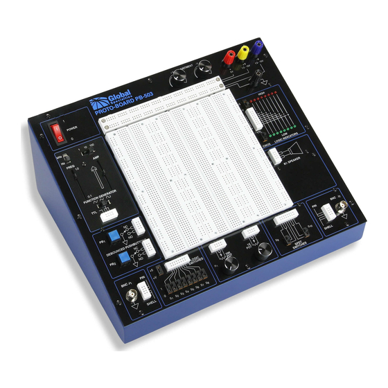
- Page 1 PB-503C Portable Analog & Digital Design Workstation Instruction Manual Revision: 2/2011...
- Page 3 Experienced designers will find the PB-503C an invaluable instrument, providing a reliable platform for the most advanced and demanding design applications. The PB-503C can be used to construct basic series and parallel circuits to the most complicated multi-stage microcomputer circuits, incorporating the latest in industrial technology.
- Page 4 PB-503C COURSEWARE Courseware is available separately through our website or as part of the PB-503C Lab package. The PB-503C Lab package offers comprehensive course instruction covering the following areas: Electronic Fundamentals Digital Electronics Fundamentals of Electricity Number Systems & Codes Binary, Decimal, Hexadecimal, Octal &...
- Page 5 ABOUT GLOBAL SPECIALTIES Thank you for selecting the Model PB-503C. Since 1973, Global Specialties has been the recognized leader in technical education courses, training equipment and tutorial materials. Our electronics and microcomputer teaching systems have proven to be effective in secondary schools, technical schools, colleges, universities and industrial training departments throughout the world.
-
Page 6: Table Of Contents
TABLE OF CONTENTS SPECIFICATIONS ..................Page 7 INTRODUCTION ..................... Page 9 DESCRIPTION OF INDIVIDUAL FEATURES ..........Page 10 CHECKING OUT THE PB-503C ..............Page 12 BREADBOARDING TECHNIQUES ..............Page 14 SERVICE & WARRANTY INFORMATION ............Page 15... -
Page 7: Specifications
SPECIFICATIONS Input Power Source AC Line: 115VAC @ 60Hz (typical) Fixed DC: +5VDC 1.0A max, current limited Ripple, <5mV Variable DC: +1.3V @150mA to +15VDC @ 500mA Ripple Power Supplies < 5mV Variable DC: -1.3VDC @ 150mA to -15VDC @ 500mA Ripple <... - Page 8 (2) Single Pull Double Throw (SPDT) - Switches uncommitted LEDs: 16 LEDs; (8) red to indicate logic high and (8) green to indicate logic low Logic High Threshold: 2.2V (nominal) in TTL/+5V mode, 70% (nominal) of selected Logic Indicators operating voltage in CMOS mode Logic Low Threshold: 0.8V (nominal) in TTL/+5V mode, 30% (nominal) of selected operating voltage in CMOS mode...
-
Page 9: Introduction
The PB-503C eliminates the clutter and confusion that often results when constructing sophisticated circuits. Alligator clips and similar connectors are seldom needed. Sockets on the PB-503C allow insertion of components or wires of up to 20 gauge. A detailed panel layout and description of the PB-503C is given in the section... -
Page 10: Description Of Individual Features
DESCRIPTION OF INDIVIDUAL FEATURES In order to properly use the full capabilities of the PB-503C, it is highly recommended that the user become familiar with the panel layout and the features of the components. (See Figure 1) POWER SUPPLIES By combining the three DC power supplies on the PB-503C, the user may work with virtually any type of integrated circuit or discrete component. - Page 11 All leads for both potentiometers are available and uncommitted. BNC CONNECTORS The PB-503C may be connected to other pieces of equipment via two BNC connectors. This allows the use of shielded cable to minimize noise and interference. SWITCHES Two single pole, double throw (SPDT) switches are provided for general switching functions.
-
Page 12: Checking Out The Pb-503C
CHECKING OUT THE PB-503C The PB-503C may be checked out for proper operation by making a few simple measurements and connections. Begin by connecting the AC line cord to a suitable receptacle. The AC power indicator should light when the power switch is turned on. - Page 13 the low (logic "0") position. Move each switch between its high and low position to verify proper functioning. Switch the logic switch +5/+V high level switch to +V and the logic indicator +5/+V operating voltage switch to +V; the relationship between the switch positions and the logic indicator display should remain the same, regardless of the setting of the 1.3 - 15 volts +V supply.
-
Page 14: Breadboarding Techniques
BREADBOARDING TECHNIQUES This section contains information which may prove useful when constructing circuits using the PB-503C. While there are no hard and fast rules for breadboarding, the following tips may save time and trouble. Unless a circuit is being prepared for a demonstration or display, avoid cutting component leads very short. -
Page 15: Service & Warranty Information
Yorba Linda, CA 92887 800-572-1028 globalspecialties.com Global Specialties will service and repair this instrument free of charge for a period of 3 full years, subject to the warranty conditions below. WARRANTY Global Specialties warrants the PB-503C to be free from defective material or workmanship for a period of 3 full years from date of original purchase. - Page 16 responsibility for errors or omissions. Neither is any liability assumed for damages resulting from the use of the information contained herein.
Need help?
Do you have a question about the PB-503C and is the answer not in the manual?
Questions and answers