
Related Manuals for Global Specialties PB-507


Summary of Contents for Global Specialties PB-507
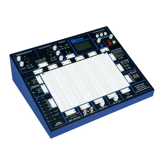
- Page 1 PB-507 Advanced Analog & Digital Electronic Design Workstation Instruction Manual Revision: 2/2014...
-
Page 2: Features & Applications
The PB-507 Advanced Analog & Digital Electronic Design Workstation is a versatile electronics trainer used in all levels of electronics instruction and design. The PB-507 enables the designing of digital and analog circuits in a fun, simple, easy-to-visualize manner. Utilizing the PB-507, students will learn valuable hands-on breadboarding techniques and build a solid foundation in circuit experimentation, construction and analysis. -
Page 3: About Global Specialties
Global Specialties' products are available from electronics distributors worldwide. Please visit to explore the many options available for the globalspecialties.com PB-507, such as courseware, pre-formed jumper wire kits, test probes and prototyping accessories. -
Page 4: Table Of Contents
TABLE OF CONTENTS 1 FEATURES & APPLICATIONS ..............2 2 ABOUT GLOBAL SPECIALTIES ..............3 3 SPECIFICATIONS ................... 5 4 INTRODUCTION ..................... 6 5 START UP ....................... 7 6 DESCRIPTION OF INDIVIDUAL FEATURES ..........8 Function Generator ......................9 Pulse Generator ......................12 Frequency counter ...................... -
Page 5: Specifications
DC Power supplies calibration ..................37 8.3.1 Step 1 ........................37 8.3.2 Step 2 ........................38 8.3.3 Step 3 ........................38 8.3.4 Step 4 ........................39 9 INFO, WARNING, AND ERROR MESSAGES ..........39 Info messages ....................... 39 Warning messages ......................40 Error messages ...................... -
Page 6: Introduction
New on the PB-507 is a LCD screen that displays the settings for each of the modules. Simply touch a control switch on any module, and the LCD switches to report the settings from that module. -
Page 7: Start Up
Most components including the breadboard are flush with the surface giving greater protection. Reliable digital circuitry is used throughout. A detailed panel layout and description of the PB-507 is given in the section "Description of Individual Features". 5 START UP At power on the PB-507 Trainer displays the Global Specialties logo and the “Initializing…”... -
Page 8: Description Of Individual Features
507 is set to load the last saved state, then the last panel used before powering off the device will be loaded at next power on. If PB-507 is set to load the default configuration, then the Function generator panel will be loaded. -
Page 9: Function Generator
6.1 Function Generator Front-panel controls Figure 2 shows the Function Generator and Pulse Generator controls on the front panel of the trainer. Figure 2... - Page 10 Frequency knob: changes the value of frequency between 0.1 Hz and 1.000MHz. Level knob: changes the value of the level in the range between 0.1 Vpp and 10.0 Vpp into 600 Ω load (0.2 to 20.0 Vpp in open circuit). ...
- Page 11 • 100.0 Hz - 999.9 Hz • 1.000 KHz – 9.999 KHz • 10.00 KHz – 99.99 KHz • 100.0 KHz – 999.9 KHz • 1 MHz. By pressing Range Up button the frequency value will be multiplied by 10 and by pressing Range Down button the frequency value will be divided by 10.
-
Page 12: Pulse Generator
Waveform The Function button can be used to select the output function in the following order: - Sine - Triangle - Square - Sine - The current waveform is displayed on the screen. Enabling the output signal Pressing Function On/Off button enables/disables the output signal. In order to enable/disable the TTL output, the TTL button must be pressed. -
Page 13: Frequency Counter
Figure 4 Changing the parameters Frequency, Level See description from function generator. The same rules are applied for the pulse generator too. Level field displays the CMOS level of the pulse generator signal. The value with no load is displayed. Duty cycle The duty knob changes the duty cycle of the output signal between 10% and 90%, minimum step being 1%. - Page 14 Figure 5 Unipolar/Bipolar button: The type of the input signal can be changed anytime by pressing the Unipolar/Bipolar button. Description The Frequency counter module can measure the frequency of bipolar or unipolar signals. The term unipolar indicates that the signal swings from zero (ground) or a positive voltage to a higher voltage, and bipolar indicates that the signal swings above and below zero (ground).
-
Page 15: Dc Power Supplies
Figure 6 The following information is displayed in the counter panel: • The measured frequency and the corresponding period • The type of the input signal • Counter mode: AUTO or MAN • The current state of the counter: NO SIGNAL or COUNTING. 6.4 DC Power supplies Front-panel controls Figure 7 shows the DC Power Supplies controls on the front panel of the trainer. -
Page 16: Debounced Pushbuttons
Figure 8 Changing the parameters +V, -V Turn the +V knob to change the +V value. Turn the –V knob to change the –V value. The underscored digit will be changed and it will be displayed in white type inside a black box indicating the active field. Use the arrow keys to move the selection. -
Page 17: Logic Switches
Figure 9 Description PB-507 provides two open-collector output pulsers, each with 1 normally-open (NO) and 1 normally-closed (NC) output. When the pushbutton is released, the circuit is in NC state, and when the pushbutton is pressed, the circuit is in NO state. -
Page 18: Spdt Switches
Figure 10 Description PB-507 provides 8 logic debounced outputs with 2 user selectable logic families: CMOS and TTL. Each of the logic switches can be switched separately between logic high (red) and logic low (green) by pressing the buttons S7…S0. When CMOS is selected, the high level is determined by the +V voltage set for the DC power supply. -
Page 19: Logic Probe
Figure 12 Description • Eight bicolor LEDs (b7…b0) are used to indicate logic high (red) or low (green) for eight digital inputs. • The TTL or CMOS input switching levels can be selected by pressing button TTL/CMOS. The High and Low thresholds for CMOS depend on the positive voltage set in the DC Power supplies module. -
Page 20: Seven Segment Displays
• MEMORY mode detects single shot events and holds indication until Pulse/Mem switch is toggled. • The TTL or CMOS input switching levels can be selected by pressing button TTL/CMOS. • The High and Low thresholds for CMOS depend on the positive voltage set in the DC Power supplies module. -
Page 21: Menu System
The function of each soft key is always shown at the bottom of the screen. The user can enter into the PB-507 main menu by pressing the “Menu” soft key. The menu will be exited automatically if no action had been present for about 60 seconds. -
Page 22: Configuration Menu
7.1 Configuration menu Table 2 shows the Configuration menu. First level Second level Third level Description Back Go Back to the PB-507 main menu Display Back Go Back to the first level settings Contrast Select Contrast to change the adjustment trainer display contrast. -
Page 23: Contrast Adjustment
7.1.2 Power-on setting You can select the PB-507 settings that are restored when the instrument is powered on. By default, the PB-507 Trainer is set to restore the default-setting at power-on. To change the power-on settings, use the Configuration Power on option. -
Page 24: Security
This feature allows you to enter a security code to prevent accidental or unauthorized calibrations or firmware updates of the PB-507 Trainer. When you first receive your PB-507 Trainer, it is secured. First you must unsecure the PB- 507 by entering the correct security code, which allows you to perform a calibration or firmware update. - Page 25 • Attach power and turn on the instrument.
-
Page 26: Lock Or Unlock Front-Panel Keys
507 will return to the initial panel Jump: if a button or an encoder from a module other than the one displayed is pressed, the panel of that module will be displayed for 3 seconds, and PB-507 will not return to the initial panel Note: If power-on option is set to Last saved state, the active panel is saved in the non-volatile memory. - Page 27 In the following table is summarized the factory default settings of the PB-507 Trainer: Parameter Factory setting Function generator Frequency 1.000 KHz Level 1.0 Vpp Waveform Sine Output On/Off TTL On/Off Pulse generator Frequency 1.000 KHz Level 1.0 V Duty cycle...
-
Page 28: Memory Menu
Table 4 7.2.1 State storage The PB-507 Trainer has ten storage locations in non-volatile memory to store states. The locations are numbered from 1 to 10. You can store a state in any of the ten storage locations, but you can only recall a state from a location that contains a stored state. -
Page 29: State Name
The following settings are saved: • Function generator: frequency, level, waveform, output On/Off, TTL On/Off • Pulse generator: frequency, level, duty cycle, CMOS On/Off, TTL On/Off • Frequency counter: input signal type • DC power supplies: positive voltage, negative voltage •... -
Page 30: Service Menu
507 Trainer. Three modules can be calibrated: Function generator, Pulse generator and DC power supplies. In order to perform the calibration procedure, the PB-507 Trainer must be unsecured. If PB-507 is secured, the “Device secured. Unsecure first.” message will appear on the display when you want to enter in calibration mode. To unsecure the PB-507 Trainer, please refer to section “Security”... -
Page 31: Step 1
Select Function generator from the calibration menu. The OUT LED will turn on, the TTL LED will turn off and PB-507 will display: Figure 17 c. Two 4 digit numbers are shown on the display. Adjust the numbers until the oscilloscope indicates the closest value to 10.0Vpp of the sine signal and the... -
Page 32: Step 3
Press the OK soft key to finish this step. The message “Step 2 done.” is displayed on the screen. 8.1.3 Step 3 a. PB-507 will display: Figure 19 b. Two 4 digit numbers are shown on the display. Adjust the numbers until the oscilloscope indicates the closest value to 1.0Vpp of the sine signal and the... -
Page 33: Step 6
Press the OK soft key to finish this step. The message “Step 5 done.” is displayed on the screen. 8.1.6 Step 6 a. PB-507 will display: Figure 22 b. Two 4 digit numbers are shown on the display. Adjust the numbers until the oscilloscope indicates the closest value to 1.0Vpp of the square signal and the... -
Page 34: Step 8
Connect the oscilloscope probe to the TTL and GND terminals of the Function generator module. b. The OUT and TTL LED will turn on and PB-507 will display: Figure 25 c. A 4 digit number is shown on the display. Adjust the number until high duration of the TTL signal is the closest value to 500 microsecond. -
Page 35: Pulse Generator Calibration
Set the DMM to measure DC voltage. Connect the DMM probe to CMOS and GND terminals of the Pulse Generator module. b. Select Pulse Generator from the calibration menu. The CMOS LED will turn on, the TTL LED will turn off and PB-507 will display:... -
Page 36: Step 2
Press the OK soft key to finish this step. The message “Step 1 done.” is displayed on the screen. 8.2.2 Step 2 a. PB-507 will display: Figure 28 c. Adjust the number until the DMM indicates the closest value to 1V. -
Page 37: Step 4
“Disconnect all loads” is displayed. Disconnect any loads connected to the trainer and press the “OK” soft key. b. Set the DMM to measure DC voltage. Connect the DMM probe to +V and GND terminals of the DC Power supplies module. PB-507 will display:... -
Page 38: Step 2
Press the OK soft key to finish this step. The message “Step 1 done.” is displayed on the screen. 8.3.2 Step 2 a. PB-507 will display: Figure 32 b. Adjust the number until the DMM indicates the closest value to 20V. -
Page 39: Step 4
8.3.4 Step 4 a. PB-507 will display: Figure 34 b. Adjust the number until the DMM indicates the closest value to -20V. c. Press the OK soft key to finish this step. The message “DC supplies calibration done.” is displayed on the screen. -
Page 40: Warning Messages
Invalid security code 9.3 Error messages PB-507 can display some specific error codes. PB-507 displays the warning message “Errors found. View error log.” each time an error is generated. This message is displayed periodically, for approximately 3 seconds in every minute. -
Page 41: Computer Interface
SPDT Switches, Counter mode, Automatic save, Power-on, Front keys, Page scrolling, Load default configuration. Note that the USB device drivers for the PB-507 device must be installed prior to running the PC application. To install the drivers, connect the PB-507 Trainer to... -
Page 42: Firmware Update
To unsecure the PB-507 Trainer, please refer to section “Security” in this manual. 3. PB-507 ask you “Are you sure you want to update the firmware?”. Press “Yes”. 4. PB-507 will enter in firmware upgrade mode. “PB-507 bootloader is running…... -
Page 43: Service And Warranty Information
Yorba Linda, CA 92887 800-572-1028 globalspecialties.com Global Specialties will service and repair this instrument free of charge for a period of 3 full years, subject to the warranty conditions below. 11.1 WARRANTY Global Specialties warrants the PB-505 to be free from defective material or workmanship for a period of 3 full years from date of original purchase. - Page 44 This warranty is in lieu of all other representations or warranties expressed or implied and no agent or representative of Global Specialties is authorized to assume any other obligation in connection with the sale and purchase of this device.
Need help?
Do you have a question about the PB-507 and is the answer not in the manual?
Questions and answers