Advertisement
Quick Links
Downloaded from www.g7syw.com
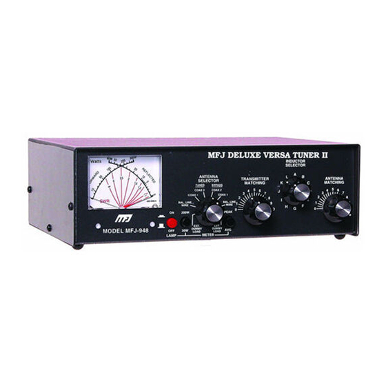
MFJ-948 Versa Tuner II
MFJ-948 Versa Tuner II
Instruction Manual
General Information
The MFJ-948 is a 300 watt RF output power antenna tuner that will match any transmitter
or transceiver to virtually any antenna. Peak or average forward and reflected power and
SWR can be read on the illuminated cross-needle meter.
The MFJ-948 uses a "T" matching network and covers all bands between 160 and 10
meters. This network will tune dipoles, inverted-vees, verticals, mobile whips, beams,
random wires, and many other antennas. The MFJ-948 has rear panel connectors for
coaxial, single wire or two wire feedlines. A built-in 4:1 balun allows the use of balanced
open wire, twinlead, or twin-axial feedlines.
An internal eight position antenna-selector switch selects an external 50 ohm dummy load,
two separate coaxial line outputs, or a single wire line-balanced line output. All of these
functions can be selected in tuned (with tuner's "T" network in line) or bypassed (no tuning
circuit) configurations.
Peak Reading SWR/Wattmeter
The illuminated cross-needle meter measures the peak or average FORWARD power,
REFLECTED power, and SWR.
The wattmeter is active in all the ANTENNA
SELECTOR positions. To use the wattmeter without the tuning circuit select one of the
ANTENNA SELECTOR positions under BYPASS.
The meter's full scale forward and reflected power range is controlled by the left METER
switch that selects 300W or 30W. If your transmitter runs more than 30 watts of output
power, set this switch to 300W (in position). If your transmitter has less than 30 watts of
output, set this switch to the 30W switch position (out).
Peak envelope power (PEP) is measured when the PEAK or AVERAGE METER push
button (right-hand side) in placed in the PEAK (in) position. Peak power and average
power values are equal with steady unmodulated carriers, FSK, or FM. The PEP power is
twice the average power with SSB two tone test modulation, and may be any amount larger
than the average power with SSB voice signals.
Forward power is displayed on the left-hand FORWARD meter scale. This scale is
calibrated from 0 to 300 watts and is read directly in the 300 watt position. Each picket
(scale mark) represents 25 watts between 300 and 100 watts, 10 watts between 100 and 10
watts, and has a single 5 watt picket below 10.
1
www.g7syw.com
Advertisement

Related Manuals for MFJ Enterprises MFJ-948


Summary of Contents for MFJ Enterprises MFJ-948
- Page 1 Instruction Manual General Information The MFJ-948 is a 300 watt RF output power antenna tuner that will match any transmitter or transceiver to virtually any antenna. Peak or average forward and reflected power and SWR can be read on the illuminated cross-needle meter.
- Page 2 Downloaded from www.g7syw.com MFJ-948 Versa Tuner II In the 30W position the forward power scale must be divided by 10. Each picket represents 1/2 watt below 1 watt, 1 watt from 1 to 10 watts, and 2.5 watts from 10 to 30 watts.
- Page 3 RF voltages may also damage anything contacting or within a half inch of the terminals. 2. Install the MFJ-948 between the transmitter and antenna as shown in the diagram above. Use a 50 ohm coaxial cable to connect the transmitter or transceiver to the SO- 239 (UHF female) labeled TRANSMITTER on the back of the tuner.
- Page 4 5. A balanced feedline (twin lead, open wire, or twin-axial line) may be connected to the two binding posts marked BALANCED LINE. Connect a jumper wire from the WIRE binding post, as indicated by the dotted line on the MFJ-948, to one of the BALANCED LINE posts. This connection activates the internal 4:1 balun.
- Page 5 MFJ-948 Versa Tuner II Adjustment Procedure When using the MFJ-948 in receive only applications, adjust the MFJ-948 for the highest "S" meter or signal level. The Tuning Chart can be used as a starting reference. To use the MFJ-948 for transmitting, follow the steps below: 1.
- Page 6 Downloaded from www.g7syw.com MFJ-948 Versa Tuner II 4. Carefully adjust the TRANSMITTER and ANTENNA MATCHING controls for the lowest reflected power. NOTE: These controls interact. Adjust the TRANSMITTER control for minimum, then adjust the ANTENNA control for minimum SWR. Go back and forth between these adjustments as many times as required until the lowest reflected power (best SWR) is obtained.
- Page 7 Antenna Hints WARNING: For operator safety a good outside earth ground or water pipe ground should ALWAYS be installed and connected to the case of the MFJ-948. Make certain the safety ground also connects to the transmitter and other station accessories. A wing nut post marked GROUND is provided for ground connection(s).
- Page 8 Downloaded from www.g7syw.com MFJ-948 Versa Tuner II Matching Problems Most matching problems occur when the antenna system presents an extremely high impedance to the tuner. When the antenna impedance is much lower than the feedline impedance, an odd quarter-wavelength feedline converts the low antenna impedance to a very high impedance at the tuner.
- Page 9 You can also send questions by mail to MFJ Enterprises, Inc., 300 Industrial Park Road, Starkville, MS 39759; by FAX to 601-323-6551; or by email to mfj@mfjenterprises.com.
- Page 10 Downloaded from www.g7syw.com MFJ-948 Versa Tuner II Schematic www.g7syw.com...
Need help?
Do you have a question about the MFJ-948 and is the answer not in the manual?
Questions and answers