
Related Manuals for YARD Commander YTL31105

Summary of Contents for YARD Commander YTL31105
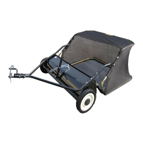
- Page 1 YTL31105 YTL31108 YTL31105O YTL31105Y TOW-BEHIND LAWN SWEEPER Instruction & Assembly SAVE THESE INSTRUCTIONS FOR FUTURE REFERENCE REV051515...
-
Page 2: Table Of Contents
Table of Contents General Warnings and Rules………………………………………………….3, 4 Controls and Features Identification…………………………………………….5 Component & Hardware……………………………………………………….6, 7 Assembly Instructions…………………………………….8, 9 10, 11, 12, 13, 14 Operation Instructions………………………………………………………..15 Maintenance and Storage…………………………………………………..16, 17 Specification……………………………………………………………………...18 Parts Drawing & Parts List………………………………………………….19, 20 Limited Warranty…………………………………………………………………21 - 2 -... -
Page 3: General Warnings And Rules
GENERAL WARNINGS READ and UNDERSTAND this manual completely before using the Lawn Sweeper. Operator must read and understand all safety and warning information, operating instructions, maintenance and storage instructions before operating this equipment. Failure to properly operate and maintain the lawn sweeper could result in serious injury to the operator or bystanders. Operation Warnings ... - Page 4 Hazard Signal Word Definitions This is the safety alert symbol. It is used to alert you to potential personal injury hazards. Obey all safety messages that follow this symbol to avoid possible injury or death. DANGER indicates an imminently hazardous DANGER situation which, if not avoided, will result in death or serious injury.
-
Page 5: Controls And Features Identification
Controls and Features Identification Read this owner’s manual before operating the equipment. Familiarize yourself with the location and function of the controls and features. Save this manual for future reference. 1) Hand Lever – Adjust the Brush Height. 2) Nylon Hopper – Holds all types of Debris. 3) Tires / Wheel –... -
Page 6: Component & Hardware
CAUTION Read and follow all instructions for assembly and operation. Failure to properly assemble this equipment could result in serious injury to the user or bystanders, or cause equipment damage . LAWN SWEEPER COMPONENT PARTS AND ASSEMBLY Take all parts out of the shipping crate and inspect components to ensure there are no missing pieces before starting to assemble the sweeper follow steps 1 through 8. - Page 7 Component and Hardware Parts REF. QTY. REF. QTY. DESCRIPTION DESCRIPTION Hitch Tube (RH) Bag Frame Strap Hitch Tube (LH) Hopper Support Rod Handle Assembly Lower Hopper Side Tube Hitch Bracket (Straight) Rear Hopper Tube Hitch Bracket Upper Hopper Side Tube Hopper Bag Rope Connecting Rod...
-
Page 8: Assembly Instructions
Assembly Instructions STEP 1: Attach the Angle Bracket to Sweeper Housing 1. Assemble the angle bracket to the sweeper housing using M8x16 hex bolt and M8 hex lock nut. NOTE: Make sure the bracket is turned as shown and aligned straight with the housing and tighten. - Page 9 STEP 3: Fasten Hitch Tubes Together 1. Fasten both hitch tubes together using two M8x65 hex bolts and M8 lock nuts. Loosely tighten. STEP 4: Attach Hitch Bracket to the Hitch Tubes 1. Attach the hitch bracket to the hitch tubes using two M8x50 hex bolts and M8 hex lock nuts. The bolts should straddle the front hitch tube bolt.
- Page 10 STEP 5: Assemble the Handle Assembly 1. Attach the height adjustment handle to the height adjustment tube using two M8x40 hex bolts and M8 lock nut. Loosely tighten. 2. Insert a M8x20 hex bolt through the angle bracket. In the following order put the spacer bushing, height adjustment strap, Ø8 big flat washer and M8 lock nut and tighten.
- Page 11 3. Insert the two upper hopper side tubes through the stitched flaps on each side of the bag. 4. Insert the ends of the rear hopper tube onto the ends of the upper hopper side tubes. Fasten together using the plastic plug. 5.
- Page 12 10. Insert the bag frame strap into the stitched sleeve along the front edge of the bag bottom. 11. Attach the bag frame strap to the lower hopper side tubes using two Ø6X37 clevis pins and two hair cotter pins Ø2. 12.
- Page 13 15. Feel along the stitched flap on the hopper bag to locate the lower hole in each upper hopper side tube. Place a hole through both sides of the stitched flaps in alignment with the lower hole. 16. Insert a Ø8X59.5 clevis pin through the lower hole in each of the upper hopper side tubes. 17.
- Page 14 STEP 8: Attach Hopper Bag to Sweeper 1. Slide the ends of the bag arms tubes into the ends of the sweeper’s hitch tubes and secure using two Ø6X37 clevis pins and hair cotter pins Ø2. 2. Tighten all hardware before using the sweeper. - 14 -...
-
Page 15: Operation Instructions
Operation Instructions WARNING Before operating or using the sweeper, review the instructions below and safety information. Failure to follow these instructions may result in property damage or injury to the operator or bystanders. ATTACH SWEEPER TO TOW VEHICLE 1. Make sure the tow vehicle and sweeper are on a level surface. 2. -
Page 16: Maintenance And Storage
Maintenance and Storage WARNING Improper maintenance and storage of the sweeper may void your warranty. MAINTENANCE After each use clean material out of hopper. Rinse/dry inside and outside of the sweeper after each use. Remove any material which has wrapped around the brushes. ... - Page 17 BRUSH REPLACEMENT 1. Remove the hopper bag from lawn sweeper. 2. Only replace one brush at a time. 3. Tip the sweeper forward on housing. Do not remove the hex bolts from double brush retainers. 4. Loosen hex bolts and hex lock nuts from single brush retainers. Slide brush out of retainers, making note of over-lap bristles position.
-
Page 18: Specification
Specifications Frame Construction…………………………………………………………..Steel Hopper Construction……………………………………………….…Nylon Mesh Hitch Type…………………………………………………………………Pin Style Wheel Type………………………………………………………Semi-Pneumatic YTL 31105 Working Width……………………………………………………...38” YTL31105 Wheel Size………………………………………………………….10” YTL31108 Working Width………………………………………………………42” YTL31108 Wheel Size………………………………………………………..10.5” - 18 -... -
Page 19: Parts Drawing & Parts List
Parts Drawing & Parts List - 19 -... - Page 20 Parts Drawing & Parts List Part No Description Qty. Part No Description Qty. Hopper Rope Hex Bolt M6x12 Vinyl Cap Dust Cover Retainer Hopper Frame Tube (Rear) Inside Star Washer Bag Frame Strap Brush Shaft Bushing Hopper Support Rod Spacer Bushing Hopper Bag Spacer for Axle Lock Washer Ø10...
-
Page 21: Limited Warranty
Limited Warranty Warranty For one year from the date of purchase YTL International will replace for the original purchaser, or repair the lawn sweeper. The warranty will not apply to any unit which was not assembled correctly, misused, overloaded or which has been used or operated contrary to our instructions, or which has been repaired or altered by anyone other than an authorized representative.
Need help?
Do you have a question about the YTL31105 and is the answer not in the manual?
Questions and answers
How can I get a manual for a yard commander 38 inch to see parts?