
Related Manuals for ALC Connect Plus AHS616


Summary of Contents for ALC Connect Plus AHS616
- Page 1 Wireless Security System Models: AHS616/AHS617 User Guide Please read these instructions completely before operating this product.
- Page 2 IMPORTANT MODEL NUMBER INFORMATION This manual covers separate devices. This manual may contain information on a device that is not included for your system but can be purchased separately by visiting: ALCWireless.com See pages 5 and 6 for information on what is included with your system.
-
Page 3: Table Of Contents
INSTALLATION ........................12 Installation Tips ........................12 Installing the Door/Window Sensor ..................13 Installing the Siren ......................13 Installing the Motion Detector ...................14 ALC CONNECT APP STATUS SCREEN ................15 Basic Operation .......................15 ALC CONNECT APP SCENARIO SCREEN ..............20 Remote Control Function ....................20 Scenario ..........................21 Shortcut ..........................22... -
Page 4: Important Safety Instructions
IMPORTANT SAFETY INSTRUCTIONS PRODUCT SAFETY: When used in the directed manner, this unit has been designed and manufactured to ensure your personal safety. Improper use of this product can result in potential electrical shock or fire hazards. Please read all safety and operating instructions carefully before installation and use, and keep these instructions handy for future reference. - Page 5 IMPORTANT SAFETY INSTRUCTIONS Recycling and Disposal Information: • Do not dispose of electronic devices or any of their components (especially batteries and LCD displays) in your municipal trash collection. • Consult your local waste management authority or a recycling organization like Earth911.com to find an electronics recycling facility in your area.
- Page 6 IMPORTANT SAFETY INSTRUCTIONS CAUTION: Maintain electrical safety. Power line operated equipment or accessories connected to this product should bear the UL listing mark or CSA certification mark on the accessory itself and should not be modified so as to defeat the safety features. This will help avoid any potential hazard from electrical shock or fire.
-
Page 7: Introduction
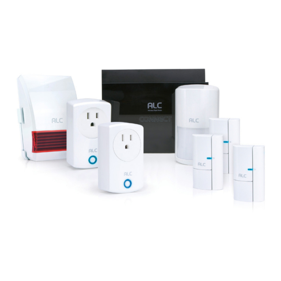
INTRODUCTION System Contents - AHS616 After unpacking, you will have the following items: Control Hub Adaptor DC 12V/1A Ethernet Cable Motion Detector Battery AA 1.5V Sticky Pad Set Power Switch Door/Window Sensor Battery CR2032 Sticky pad Set Indoor Siren Adaptor DC 5V/1 A Bracket Screw Set Remote Control... - Page 8 INTRODUCTION System Contents - AHS617 After unpacking, you will have the following items: Control Hub Adaptor DC 12V/1A Ethernet Cable Motion Detector Battery AA 1.5V Sticky Pad Set Power Switch Door/Window Sensor Battery CR2032 Sticky pad Set Indoor Siren Adaptor DC 5V/1 A Bracket Screw Set —...
-
Page 9: Getting To Know Your Security System
INTRODUCTION Getting to Know Your Security System The AHS616 and AHS617 are upgradeable security systems that come with everything you need to start protecting your home. You can increase security at any time by adding additional sensors and/or cameras. The system is easily accessed anywhere in the world via Internet. The free iOS/Android App allows you to view/record video, turn power switch(es) on/off, activate/ deactivate the siren manually or automatically. -
Page 10: Getting Started
Download the ALC Connect Plus App as follows: APPLE DEVICE: From your iPhone or iPad, go to the App Store and search for ALC Connect Plus. ANDROID DEVICE: From your Android smartphone or tablet device, go to Google Play and search for ALC Connect Plus. -
Page 11: Connecting To The Control Hub
GETTING STARTED Connecting to the Control Hub Connect the supplied Ethernet cable Connect one end of the AC Adaptor from the router to the Ethernet jack on to the DC IN jack on the rear of the the back of the Control Hub. Control Hub and the other end to a 120 volt AC (standard indoor) power outlet;... - Page 12 GETTING STARTED Connecting to Control Hub Name the system (i.e. “Home System”) Enter a Security Code (must be 6 and add a photo (if desired). Tap characters or more, letters and/or Next. numbers). Repeat and then tap Save. P1S4 P1S5 Carrier 9:41 AM Carrier...
- Page 13 GETTING STARTED Connecting to Control Hub The included sensors have already Tap on each sensor to edit the name been paired to your Hub. Now we will and location for each. Such as Door need to name and provide a location Sensor, Front Door or Power Switch, for each.
-
Page 14: Installation
INSTALLATION Installation Tips The diagram below shows the suggested location(s) for the security system. Use this as a guide for your installation. The system is expandable with additional compatible wireless cameras, Motion Detectors, door/window contact sensors, sirens or other sensors (see pages 5 and 6 to see what is included with your kit) for greater protection. -
Page 15: Installing The Door/Window Sensor
INSTALLATION Installing the Door/Window Sensor Double-Sided Tape Select a location on a door or window. The large section of the Apply the double-sided tape to the sensor should be fixed on the rear of both sections of the Door/ immovable frame of the door/window. Window sensor. -
Page 16: Installing The Motion Detector
INSTALLATION Installing the Motion Detector Option A - Double-Sided Tape Select a desired location. It is recommended to place the Motion Apply the double-sided tape to the Detector in the corner of the room rear of the Motion Detector as shown. and between 6 to 8 feet from the Use the thick tape for flat wall mount floor. -
Page 17: Alc Connect App Status Screen
ALC CONNECT APP STATUS SCREEN Basic Operation When first turning on the app you The Status screen will then appear; will enter the Control Hub Selection see below and the following pages window. Simply tap your Control Hub for the details and operation of the to enter. - Page 18 ALC CONNECT APP STATUS SCREEN Basic Operation Tap a sensor/device’s name to enter the respective device’s Edit window, which will allow you to set the following: Power Switch: Name and Location. You can also set the Auto Off Time (when set with a scenario) as well as a schedule to turn on and off.
- Page 19 ALC CONNECT APP STATUS SCREEN Basic Operation PANIC: Tap the Panic icon on the For Main Settings: At the Status Status screen to set off the Alarm. Screen, tap then enter the Admin Password (Default is 123456) to enter the Advanced settings as described on the next page.
- Page 20 ALC CONNECT APP STATUS SCREEN Basic Operation MAIN SETTINGS Set the following at the Device’s Advanced Settings: Control Hub Siren Volume: Tap to set the Control Hub’s Siren Volume (None, Low or High). Control Hub Siren Duration: Tap to set the Control Hub’s Siren Duration (60, 120 or 180 seconds).
- Page 21 ALC CONNECT APP STATUS SCREEN CAMERA SETTINGS Basic Operation (Camera Available Separately) Set the following at the Camera’s Advanced Settings: Admin Password: Tap to change the Admin Password. Device Security Code: Tap to change the Device Security Code. Cloud Setting: Any cloud storage criteria will appear here (i.e.
-
Page 22: Alc Connect App Scenario Screen
ALC CONNECT APP SCENARIO SCREEN Remote Control Function For the Remote Control to work, it must be within range of your Hub. Primarily it is used when before entering and leaving the house to Disarm or Arm your System. -
Page 23: Scenario
ALC CONNECT APP SCENARIO SCREEN Scenario On the Status window, tap the The Scenario will allow you to preset Scenario icon. a sequence of events. For example, once the Motion Detector detects motion, the camera can begin recording and the light can turn on. -
Page 24: Shortcut
ALC CONNECT APP SCENARIO SCREEN Scenario Select the desired device to activate by tapping its check box. Note that adding a device will automatically activate it. Tap Save when done. Shortcut A Shortcut can be created to group sensors together to turn them on all at the same time. -
Page 25: Pairing
PAIRING Pairing the Door/Window Sensor PAIRING: All included sensors are paired with the Control Hub at the factory. See following pages to pair them again or if additional accessories are purchased. The Door/Window Sensor comes with At the dashboard, tap “+” (Add Device). a pre-installed CR2032 battery. -
Page 26: Pairing The Motion Detector
PAIRING Pairing the Motion Detector The Motion Detector comes with At the dashboard, tap “+” (Add Device). three pre-installed AA batteries. If they need replacing, press the tab at the bottom of the sensor and insert three AA size batteries following the diagram in the compartment. -
Page 27: Pairing The Power Switch
PAIRING Pairing the Power Switch At the dashboard, tap “+” (Add De- Tap Power Switch from the Device vice). list. Name the Power Switch and the location, tap Next. Carrier 9:41 AM 100% Tap Pair to start pairing the Power Name the Power Switch and location and tap Save. -
Page 28: Pairing The Remote Control
PAIRING Pairing the Remote The Remote Control comes with a At the dashboard, tap “+” (Add Device). pre-installed CR2032 battery. If it needs replacing, simply pull out the battery compartment on the side of the Remote Control and replace with a new CR2032 battery. -
Page 29: Pairing The Siren
PAIRING Pairing the Indoor Siren Select Indoor Siren from the Device At the dashboard, tap “+” (Add Device). List. Name the Indoor Siren and the location, tap Save. Tap Pair to initiate pairing. Plug the AC adapter to Indoor Siren. LED will flash and pairing is complete. -
Page 30: Troubleshooting
TROUBLESHOOTING If you have any trouble with your system, try these simple steps which should handle most common issues. Problem Possible Solution Make sure it is plugged into an AC Outlet and that the rear connection is inserted correctly. Control Hub Device not working. -
Page 31: Factory Default/Reset
TROUBLESHOOTING Factory Default/Reset Insert a paper clip or similar object into the Reset hole for 12 seconds and the system will start the reset process. The system will restore to factory default settings and you may start the setup. — 29 —... -
Page 32: Product Specifications
PRODUCT SPECIFICATIONS Control Hub Operation Voltage ....................12V DC/1A Ethenet ........................10/100 Mbps Sub-1G ........................916.8 MHz LED ....................... Max Standby 8hr Remote Control Signal Frequency ....................916.8 MHz RF Range (open field conditions) ..................150 M Battery Type ................1 x CR2032 Battery (included) Battery Life .........Anticipated life up to 2 years (Supposed 10 triggers per day) Battery Power Monitoring ...........Yes (On device and transmitted to App) Operating Temperature .................... -
Page 33: Power Switch
PRODUCT SPECIFICATIONS Power Switch Signal Frequency ....................916.8 MHz RF Range (open field conditions) ................ 500 ft (150 M) Load Switching Capability .................... 1800W Operating Temperature ..................... 0°~40°C Operating Humidity ................... 10%~80% RH Dimensions ..............3.7 x 2.2 x 1.2 in (94 x 55 x 31 mm) Door/Window Sensor Signal Frequency ......................916.8MHz RF Range (open field conditions) ................ -
Page 34: Warranty
WARRANTY — 32 —... - Page 35 WARRANTY — 33 —...
- Page 36 Wireless Made Simple. ALCWireless.com 111519_v1...
- Page 37 Wireless Made Simple. ALCWireless.com...
Need help?
Do you have a question about the Connect Plus AHS616 and is the answer not in the manual?
Questions and answers