Table of Contents
Advertisement
OWNER'S OPERATION AND INSTALLATION MANUAL
WARNING: If the information in this manual is not
followed exactly, a fire or explosion may result causing
property damage, personal injury or loss of life.
— Do not store or use gasoline or other flammable va-
pors and liquids in the vicinity of this or any other
appliance.
— WHAT TO DO IF YOU SMELL GAS
• Do not try to light any appliance.
• Do not touch any electrical switch; do not use any
phone in your building.
• Immediately call your gas supplier from a neighbor's
phone. Follow the gas supplier's instructions.
• If you cannot reach your gas supplier, call the fire
department.
— Installation and service must be performed by a quali-
fied installer, service agency or the gas supplier.
WARNING: This appliance is equipped for Natural and
Propane gas. Field conversion is not permitted other than
between natural or propane gases.
Questions, problems, missing parts? Before returning to your retailer, call
our customer service department at 1-855-607-6557, 8:00 am - 4:30 pm EST,
Monday through Friday or email info@factorybuysdirect.com
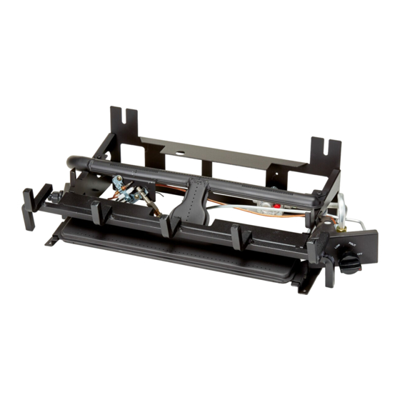
VENT-FREE GAS
LOG CHASSIS
DUAL FUEL THERMOSTAT
MODEL
FDLT24/30-1
Advertisement
Table of Contents

Related Manuals for Duluth Forge FDLT24-1

Summary of Contents for Duluth Forge FDLT24-1
- Page 1 VENT-FREE GAS LOG CHASSIS OWNER’S OPERATION AND INSTALLATION MANUAL DUAL FUEL THERMOSTAT MODEL FDLT24/30-1 WARNING: If the information in this manual is not followed exactly, a fire or explosion may result causing property damage, personal injury or loss of life. —...
-
Page 2: Table Of Contents
TABLE OF CONTENTS Safety ............3 Operation ..........19 Qualified Installing Agency ......4 Inspecting Burners........21 Specifications ..........5 Care And Maintenance ......22 Product Features ........5 Troubleshooting ........23 Product Identification ......... 5 Replacement Parts ........27 Local Codes.......... -
Page 3: Safety
SAFETY WARNING: Any change to IMPORTANT: Read this owner’s manual carefully and completely this heater or its controls can before trying to assemble, op- be dangerous. erate, or service this heater. WARNING: Do not allow fans Improper use of this heater can to blow directly into fireplace. -
Page 4: Qualified Installing Agency
SAFETY 1. Do not place Propane/LP supply tank(s) 10. Operating heater above elevations of inside any structure. Propane/LP supply 4,500 feet could cause pilot outage. tank(s) must be placed outdoors. 11. To prevent performance problems, do 2. This heater shall not be installed in a not use propane/LP fuel tank of less than bedroom or bathroom. -
Page 5: Specifications
SPECIFICATIONS Model FDLT24/30-1 Ignition Electronic Piezo Ignitor Gas Type Natural Gas Propane Gas Maximum Input Rating 33,000 Btu/Hr 33,000 Btu/Hr Minimum Input Rating 25,000 Btu/Hr 20,000 Btu/Hr Manifold Pressure 4" W.C. 9" W.C. Inlet Gas Pressure* (inches Max. 9.5" Max. 14" of water) (*for purposes of Min. -
Page 6: Local Codes
LOCAL CODES Install and use heater with care. Follow all State of Massachusetts: The installation local codes. In the absence of local codes, must be made by a licensed plumber or use the latest edition of The National Fuel gas fitter in the Commonwealth of Mas- Gas Code, ANSI Z223.1/NFPA 54*. -
Page 7: Air For Combustion And Ventilation
AIR FOR COMBUSTION AND VENTILATION WARNING: This heater shall WARNING: This heater shall not be installed in a room or not be installed in a confined space space unless the required vol- or unusually tight construction ume of indoor combustion air unless provisions are provided is provided by the method de- for adequate combustion and... - Page 8 AIR FOR COMBUSTION AND VENTILATION VENTILATION AIR Ventilation Air From Inside Building Ventilation Air From Outdoors Provide extra fresh air by using ventilation This fresh air would come from an adjoining grills or ducts. You must provide two perma- unconfined space. When ventilating to an nent openings: one within 12"...
-
Page 9: Installation
INSTALLATION NOTICE: This heater is intended WARNING: Never install the for use as supplemental heat. heater Use this heater along with your • in a bedroom or bathroom primary heating system. Do not • in a recreational vehicle install this heater as your pri- •... - Page 10 INSTALLATION IMPORTANT: Vent-free heaters add moisture to the air. Although this is beneficial, installing heater in rooms without enough ventilation air may cause mildew to form too much moisture. See Air for Combustion and Ventilation, pages 7 and 8. Before beginning assembly or operation of the product, make sure all parts are present.
- Page 11 INSTALLATION If Using Mantel at least 8" up. If noncombustible material is less than 12", you must install the fireplace You must have noncombustible material(s) hood accessory. Even if noncombustible above the fireplace opening. Noncombustible material is more than 12", you may need the materials (such as slate, marble, tile, etc.) hood accessory to deflect heat away from must be at least 1/2"...
- Page 12 INSTALLATION FLOOR CLEARANCES A. If installing appliance on the floor level, B. If combustible materials are less than 14" you must maintain the minimum distance to the fireplace, you must install appliance of 14" to combustibles (see Figure 8). at least 5" above the combustible flooring (see Figure 9).
- Page 13 INSTALLATION GAS SELECTION Insert Gas Fitting This appliance is factory Blue Propane/ for Propane/LP Gas LP Gas Plunger preset for propane/LP gas. Underneath No changes are required for Dust Cover connecting to propane/LP. Only a qualified installer or service technician can perform gas selec- tion and connecting to gas supply.
- Page 14 INSTALLATION 2. Apply thread sealant to the threads on Use only the cap supplied on the the connection fitting. While pushing in, regulator. Do not use an off the rotate the fitting clockwise until the threads shelf pipe plug. This can damage engage the regulator.
- Page 15 INSTALLATION CONNECTING TO GAS SUPPLY WARNING: A qualified ser- CAUTION: For natural gas, vice technician must connect check your gas line pressure heater to gas supply. Follow all before connecting heater to gas local codes. line. Gas line pressure must be no greater than 9.5"...
- Page 16 INSTALLATION Typical Inlet Pipe Diameters Install sediment trap in supply line as shown Use 3/8" black iron pipe or greater. Installa- in Figure 13. Place sediment trap where it is tion must include an equipment shutoff valve, within reach for cleaning. Place sediment trap union, and plugged 1/8"...
- Page 17 INSTALLATION CHECKING GAS CONNECTIONS WARNING: Never use an open WARNING: Test all gas piping flame to check for a leak. Apply and connections, internal and a noncorrosive leak detection external to unit, for leaks after fluid to all joints. If bubbles form, installing or servicing.
- Page 18 INSTALLATION PRESSURE TESTING HEATER GAS CONNECTIONS 1. Open equipment shutoff valve (see Figure 17, page 17). Apply a noncorrosive leak 15, page 17). detection fluid to all joints. Bubbles form- ing show a leak. 2. Open main gas valve located on or near gas meter for natural gas or open pro- 5.
-
Page 19: Operation
OPERATION FOR YOUR SAFETY READ BEFORE LIGHTING not use any phone in your building. WARNING: If you do not fol- • Immediately call your gas supplier low these instructions exactly, a from a neighbor’s phone. Follow the fire or explosion may result caus- gas supplier’s instructions. - Page 20 OPERATION 8. Turn control knob counterclockwise CAUTION: Do not try to ad- to the desired heating level. The main just heating levels by using the burner should light. Set control knob to equipment shutoff valve. any heat level between 1 (LO) and 5 (HI). Note: Please wait one minute after shut- ting off heater to allow the control valve WARNING: If input gas...
-
Page 21: Inspecting Burners
INSPECTING BURNERS IMPORTANT: Owner’s should check pilot flame pattern and burner flame pattern often. Incorrect flame patterns indicate the need for cleaning (see Care and Maintenance, page 22) or service. WARNING: Only a qualified service person should service and repair heater. This includes maintenance requiring replacement or alteration of components. -
Page 22: Care And Maintenance
CARE AND MAINTENANCE WARNING: Turn off heater and let cool before servicing. CAUTION: You must keep control areas, burner, and circulating air passageways of heater clean. Inspect these areas of heater before each use. Have heater inspected yearly by a qualified service techni- cian. -
Page 23: Troubleshooting
CARE AND MAINTENANCE ODS/PILOT Ignitor Use a vacuum cleaner, pressurized air, or a Natural Gas Thermocouple Electrode small, soft bristled brush to clean. Burner Propane/LP A yellow tip on the pilot flame indicates dust Gas Burner and dirt in the pilot assembly. There is a small pilot air inlet hole about 2"... - Page 24 TROUBLESHOOTING Problem Possible Cause Corrective Action Using natural gas and I n l e t p r e s s u r e e x c e e d s Bypass pressure switch. See pilot will not light. 9.5" WC. instructions below.
- Page 25 TROUBLESHOOTING Problem Possible Cause Corrective Action ODS/pilot lights but flame 1. Control knob is not fully 1. Press in control knob fully. goes out when control pressed in. knob is released. 2. Control knob is not pressed 2. After ODS/pilot lights, keep in long enough.
- Page 26 TROUBLESHOOTING Problem Possible Cause Corrective Action Slight smoke or odor 1. Residues from manufactur- 1. Problem will stop after a few during initial operation. ing process. hours of operation. Heater produces a whis- 1. Turning control knob to high 1. Turn control knob to low tling noise when burner position when burner is cold.
-
Page 27: Replacement Parts
REPLACEMENT PARTS Note: Use only original replacement parts. This will protect your warranty coverage for parts replaced under warranty. PARTS UNDER WARRANTY Contact authorized dealers of this product. • Model and serial number of your heater If they can’t supply original replacement •... -
Page 28: Parts
PARTS MODEL FDLT24/30-1 www.factorybuysdirect.com 200376-01A... - Page 29 PARTS MODEL FDLT24/30-1 This list contains replaceable parts for your heater. When ordering replacement parts, follow the instructions listed under Replacement Parts on page 27 of this manual. ITEM PART # DESCRIPTION Grate Assembly Burner Assembly 161338-01 Ignitor Ignitor Bracket “Y”...
- Page 30 NOTES ________________________________________________________________ ________________________________________________________________ ________________________________________________________________ ________________________________________________________________ ________________________________________________________________ ________________________________________________________________ ________________________________________________________________ ________________________________________________________________ ________________________________________________________________ ________________________________________________________________ ________________________________________________________________ ________________________________________________________________ ________________________________________________________________ ________________________________________________________________ ________________________________________________________________ ________________________________________________________________ ________________________________________________________________ ________________________________________________________________ ________________________________________________________________ ________________________________________________________________ ________________________________________________________________ ________________________________________________________________ ________________________________________________________________ ________________________________________________________________ ________________________________________________________________ www.factorybuysdirect.com 200376-01A...
- Page 31 NOTES ________________________________________________________________ ________________________________________________________________ ________________________________________________________________ ________________________________________________________________ ________________________________________________________________ ________________________________________________________________ ________________________________________________________________ ________________________________________________________________ ________________________________________________________________ ________________________________________________________________ ________________________________________________________________ ________________________________________________________________ ________________________________________________________________ ________________________________________________________________ ________________________________________________________________ ________________________________________________________________ ________________________________________________________________ ________________________________________________________________ ________________________________________________________________ ________________________________________________________________ ________________________________________________________________ ________________________________________________________________ ________________________________________________________________ ________________________________________________________________ ________________________________________________________________ www.factorybuysdirect.com 200376-01A...
-
Page 32: Warranty
WARRANTY KEEP THIS WARRANTY Model _______________________________ Serial No. ____________________________ Date Purchased _______________________ Keep receipt for warranty verification. REGISTER YOUR PRODUCT AT WWW.FACTORYBUYSDIRECT.COM FACTORY BUYS DIRECT LIMITED WARRANTIES New Products Standard Warranty: Factory Buys Direct warrants this new product and any parts thereof to be free from defects in material and workmanship for a period of one (1) year from the date of first purchase from an authorized dealer provided the product has been installed, maintained and operated in accordance with Factory Buys Direct’s warnings and instructions.
Need help?
Do you have a question about the FDLT24-1 and is the answer not in the manual?
Questions and answers