Table of Contents
Advertisement
Quick Links
SPECIFICATIONS
Specifications*
General
Power Supply
Current Consumption
Maximum Power Output
Power Output
Tone/SQ Adjustment Range
Speaker Impedance
Pre-Amp Output Voltage
Pre-Amp Output Impedance
Subwoofer Output Voltage
ORDER NO.ACED060109C3
AUTOMOTIVE AFTERMARKET
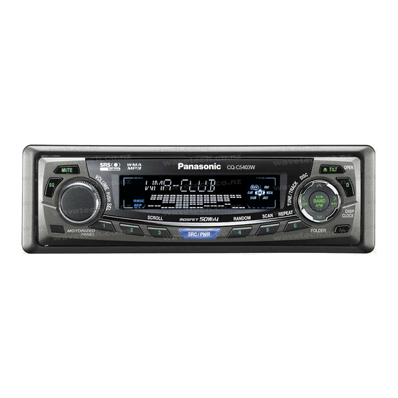
CQ-C5403W / CQ-C5303W
WMA MP3 CD Player/Receiver
DC 12V (11V - 16V),
Test Voltage 14.4V
Negative Ground
Less than 2.1A (CD mode ; 0.5W
4-channels)
50W×4 (at 1kHz)
Volume control Maximum
18W×4CH (1kHz, 1%, 4
SQ Low/Bass ; ±12dB / (at 60Hz,
80Hz, 100Hz, 200Hz)
SQ Mid ; ±12dB / (at 500Hz,
1kHz, 2kHz, 3kHz)
SQ High/Treble ; ±12dB / (at
10kHz, 12kHz, 15kHz, 18kHz)
4-8
4V (CD mode; 1kHz, 0dB)
[CQ-C5403W]
2.5V (CD mode ; 1kHz 0dB)
[CQ-C5303W]
60
[CQ-C5403W]
200
[CQ-C5303W]
4V [CQ-C5403W]
2.5V [CQ-C5303W]
1
)
Advertisement
Table of Contents

Related Manuals for Matsushita Electric CQ-C5403W

Summary of Contents for Matsushita Electric CQ-C5403W
- Page 1 ORDER NO.ACED060109C3 AUTOMOTIVE AFTERMARKET CQ-C5403W / CQ-C5303W WMA MP3 CD Player/Receiver SPECIFICATIONS Specifications* General Power Supply DC 12V (11V - 16V), Test Voltage 14.4V Negative Ground Current Consumption Less than 2.1A (CD mode ; 0.5W 4-channels) Maximum Power Output 50W×4 (at 1kHz)
- Page 2 * Specifications and the design are subject to possible modification without notice due to improvements. ** Dimensions and Weight shown are approximate. Above specifications comply with EIA standards. 2006 Matsushita Electric Industrial Co., Ltd. All rights reserved. Unauthorized copying and distribution is a violation of law.
-
Page 3: About Lead Free Solder (Pbf)
1. ABOUT LEAD FREE SOLDER (PbF) Distinction of PbF PCB: PCBs (manufactured) using lead free solder will have a PbF stamp on the PCB. Caution : - Pb free solder has a higher melting point than standard solder; Typically the melting point is 50 - 70°F (30 - 40°C) higher. Please use a soldering iron with temperature control and adjust it to 700 ±... -
Page 4: Replacing The Fuse
- Fully Motorized Face Plate. - SQ (Sound Quality). - SQ3 (3-Band Sound Quality). - SRS TruBass (CQ-C5403W). - This manual is for 2 models CQ-C5403W and CQ-C5303W. The following table describes the differences between 2 models. 4. REPLACING THE FUSE... -
Page 5: Maintenance
Use fuses of the same specified rating (15amps). Using different substitutes or fuses with higher ratings, or connecting the product directly without a fuse, could cause fire or damage to the stereo unit. 5. MAINTENANCE Your product is designed and manufactured to ensure a minimum of maintenance. Use a dry, a soft cloth for routine exterior cleaning. - Page 6 9. DISASSEMBLY INSTRUCTIONS 9.1. How to remove the Flexible PCB...
-
Page 7: Terminals Description
9.2. How to install the Main P.C.B of the Electric Slide Display 10. TERMINALS DESCRIPTION 10.1. Main Block IC601 : YESAM335... - Page 8 Port Description FM AM CD 1 BATT Battery voltage 1.9 1.9 1.9 detection 2 AMP Amp mute control O 4.8 4.8 4.8 MUTE 3 STBY Power IC stundby O 4.8 4.8 4.8 control 4 FP Panel motor O 4.7 4.7 4.7 MOTOR1 control 1 5 FP...
- Page 9 32 PLL DI PLL data...
- Page 10 Port Description FM AM CD 33 PLL CE PLL chip select 34 ST Radio station 4.8 4.8 4.8 detect 35 INI A Mode setting A 36 INI B Mode setting B 37 INI C Mode setting C 38 RM IN Remote control 4.7 4.7 4.7 data...
- Page 11 MUTE control Port Description FM AM CD 68 AF MUTE AF mute control O 4.8 4.8 4.8 69 HUB HUB control signal O 4.8 4.8 4.8 70 CH CLK / CD changer clock / SYSID3 System upgrade 71 CH DATA CD changer data 72 SYSID 1 System upgrade 4.8 4.8 4.8 73 CH REM CD changer remote O 0.9 1.2...
- Page 12 Port Descriptions AVSS LD-MT Loading Motor drive IC control 1 Loading Motor drive IC control 2 LD-EJ Loading Motor drive IC control (Eject) AMUTE Mute signal output SBSY DSP IC SBSY TXD0 Serial data output RXD0 Serial data input CLK0 Clock input DVCC Power supply (3.3V)
-
Page 13: Package And Ic Block Diagram
Port Descriptions CONT DSP IC power control 2 (P17) PIO0 DSP IC PIO0 ZDET LOAD detect CDFS Serial frame sink signal input (CD ON) P50/ Reference voltage P51/ Loading motor detect P52/ P53/ AVCC Power supply (3.3V) 11. PACKAGE AND IC BLOCK DIAGRAM 11.1. - Page 14 IC201 : YESAM289 IC271 : YESAM274...
- Page 15 IC401 : C1BB00001045 IC240,270,370 : YESAM286 (CQ-C5303W ) IC680 : YESAM265...
- Page 16 IC681 : YESAM346 IC710 : YESAM340 IC750 : YESAM267...
- Page 17 IC760 : YESAM287 IC763 : YESAM357 (CQ-C5403W) IC810 : YESAM344...
- Page 18 11.2. Display Block IC902 : YESAM264 11.3. CD Servo Block IC401,403 : YESAM341 IC402 : YESAM342 12. REPLACEMENT PARTS LIST [CQ-C5403W] Notes : 1. Be sure to make your orders of replacement parts according to this list.
- Page 19 2. Important safety notice: Components, identified by mark have special characteristics important for safety. When replacing any of these components, use only manufacturer's specified parts. 3. Location keys in the remarks column indicates the general location of the parts shown in the exploded drawing, as in a road map. 4.
- Page 20 Ref. No. Part No. Part Name & Description Remarks Q662 YESAN122 Transistor Q690 YESAN119 Transistor Q692 YESAN119 Transistor Q720 YESAN115 Q730 YESAN115 Q731 YESAN123 Transistor Q740 YESAN079 Transistor Q751 YESAN079 Transistor Q761 YESAN090 Transistor Q770 YESAN088 Transistor DIODEs D260 YESAD155 Diode D270 YESAD146...
- Page 21 Ref. No. Part No. Part Name & Description Remarks C055 YESCC482 Ceramic, 0.01 F 50WV C061 YESCC527 Ceramic, 0.022 F 25WV C062 YESCC527 Ceramic, 0.022 F 25WV C065 YESCC481 Ceramic, 0.001 F 50WV C203 YESCC333 Electrolytic, 100 F 16WV C204 YESCC333 Electrolytic, 100 F 16WV...
- Page 22 Ref. No. Part No. Part Name & Description Remarks C257 YESCC551 Electrolytic, 4.7 F 50WV C258 YESCC334 Electrolytic, 100 F 16WV C259 YESCC551 Electrolytic, 4.7 F 50WV C261 YESCC372 Electrolytic, 4.7 F 25WV C262 YESCC547 Electrolytic, 100 F 16WV C263 ECQV1H224JL2 Plastic Film, 0.22 F 50WV...
- Page 23 Ref. No. Part No. Part Name & Description Remarks C372 YESCC486 Ceramic, 0.0047 F 50WV C375 YESCC557 Ceramic, 0.47 F 16WV C378 YESCC483 Ceramic, 0.1 F 50WV C401 YESCC541 Ceramic, 12pF C402 YESCC429 Ceramic, 10pF 50WV C403 YESCC228 Ceramic, 0.1 F 16WV C404 YESCC452...
- Page 24 Ref. No. Part No. Part Name & Description Remarks C811 YESCC515 Electrolytic, 47 F 16WV RESISTORs YESRG241 Chip, 0 1/8W YESRG241 Chip, 0 1/8W YESRG241 Chip, 0 1/8W YESRG241 Chip, 0 1/8W YESRG241 Chip, 0 1/8W YESRG241 Chip, 0 1/8W YESRG241 Chip, 0 1/8W...
- Page 25 Ref. No. Part No. Part Name & Description Remarks L296 YESRG392 Chip, 4.7 1/8W L395 YESRG392 Chip, 4.7 1/8W L396 YESRG392 Chip, 4.7 1/8W R007 YESRG339 Chip, 0 R010 YESRG339 Chip, 0 R012 YESRG132 Chip, 0 1/4W R014 YESRG339 Chip, 0 R021 YESRG241 Chip, 0...
- Page 26 Ref. No. Part No. Part Name & Description Remarks R256 YESRG369 Chip, 150k 1/8W R257 YESRG369 Chip, 150k 1/8W R260 YESRG158 Chip, 100 1/10W R261 YESRG395 Chip, 56 1/8W R262 YESRG360 Chip, 10k 1/8W R263 YESRG396 Chip, 560 1/8W R265 YESRG395 Chip, 56 1/8W...
- Page 27 Ref. No. Part No. Part Name & Description Remarks R408 YESRG170 Chip, 47k 1/10W R409 YESRG159 Chip, 1k 1/4W R410 YESRG157 Chip, 0 1/10W R411 YESRG157 Chip, 0 1/10W R413 YESRG372 Chip, 1.8k 1/8W R414 YESRG396 Chip, 560 1/8W R417 YESRG334 Chip, 10 1/8W...
- Page 28 Ref. No. Part No. Part Name & Description Remarks R648 YESRG159 Chip, 1k 1/4W R649 YESRG159 Chip, 1k 1/4W R650 YESRG414 Chip, 620k 1/8W R653 YESRG251 Chip, 1.8k 1/10W R654 YESRG171 Chip, 5.1k 1/10W R655 YESRG360 Chip, 10k 1/8W R656 YESRG254 Chip, 2.7k 1/10W...
- Page 29 Ref. No. Part No. Part Name & Description Remarks R704 YESRG362 Chip, 11k 1/8W R710 YESRG341 Chip, 200k 1/10W R711 YESRG157 Chip, 0 1/10W R712 YESRG343 Chip, 30k 1/10W R714 YESRG159 Chip, 1k 1/4W R715 YESRG159 Chip, 1k 1/4W R717 YESRG340 Chip, 2k 1/10W...
- Page 30 Ref. No. Part No. Part Name & Description Remarks XL601 YESXL035 Crystal XL602 YESXL036 Crystal POSISTOR PH701 YESRTD011 Posistor SERGE PROTECTOR / VARISTOR Z050 YESRTD014 Serge Protector Z701 YESRTD012 Varistor SWITCHes SW601 YESAS125 Switch SW602 YESAS124 Switch [7220-05-12] DISPLAY BLOCK IC's and TRANSISTORs IC901 YEAMLC75884W...
- Page 31 D965 YESAD170 Ref. No. Part No. Part Name & Description Remarks D966 YESAD170 D967 YESAD170 D968 YESAD170 D969 YESAD170 CAPACITORs C901 YESCC517 Ceramic, 0.22 F 16WV C902 YESCC523 Ceramic, 0.1 F 16WV C903 YESCC523 Ceramic, 0.1 F 16WV C905 YESCC523 Ceramic, 0.1 F 16WV C906...
- Page 32 Ref. No. Part No. Part Name & Description Remarks CN911 YESAE422 Connector, 3P SWITCHes SW901 YESAS123 Switch SW902 K0H1BA000445 Switch SW903 K0H1BA000445 Switch SW904 K0H1BA000445 Switch SW905 K0H1BA000445 Switch SW906 K0H1BA000445 Switch SW907 K0H1BA000445 Switch SW908 K0H1BA000445 Switch SW909 K0H1BA000445 Switch SW910 K0H1BA000445...
- Page 33 Screw, 2.6 * 6.0 YESJS01188 Bind S Tite, 2.6*5.0 YESJS01194 Bind S Tite 3.0*6.0 YESJS01191 Bind Screw, 2.6*8 YESJS01193 Bind Screw, 3*14 YESJS01195 Camera Screw 3 2.0*4.0 YESJS01197 Cup Screw 2.0*4.0 YESJS01204 Bind S Tite, 3.0*8.0 13. EXPLODED VIEW (Unit) [CQ-C5403W]...
- Page 34 14. REPLACEMENT PARTS LIST [CQ-C5303W] Notes : 1. Be sure to make your orders of replacement parts according to this list. 2. Important safety notice: Components, identified by mark have special characteristics important for safety. When replacing any of these components, use only manufacturer's specified parts.
- Page 35 3. Location keys in the remarks column indicates the general location of the parts shown in the exploded drawing, as in a road map. 4. The marking (RTL) indicates that Retention Time is limited for this item. After the discontinuation of assembly in production, the item will continue to be available for a specific period of time.
- Page 36 Ref. No. Part No. Part Name & Description Remarks Q730 YESAN115 Q740 YESAN079 Transistor Q751 YESAN079 Transistor Q761 YESAN090 Transistor Q770 YESAN088 Transistor DIODEs D260 YESAD155 Diode D270 YESAD146 Diode D271 YESAD146 Diode D272 YESAD146 Diode D273 YESAD146 Diode D274 YESAD146 Diode D275...
- Page 37 Ceramic, 0.022 F 25WV...
- Page 38 Ref. No. Part No. Part Name & Description Remarks C065 YESCC481 Ceramic, 0.001 F 50WV C203 YESCC333 Electrolytic, 100 F 16WV C204 YESCC333 Electrolytic, 100 F 16WV C205 YESCC434 Ceramic, 330pF 50WV C206 YESCC549 Electrolytic, 2.2 F 50WV C207 YESCC434 Ceramic, 330pF 50WV C210 YESCC546...
- Page 39 Ref. No. Part No. Part Name & Description Remarks C320 YESCC537 Electrolytic, 4.7 F 25WV C325 YESCC537 Electrolytic, 4.7 F 25WV C340 YESCC537 Electrolytic, 4.7 F 25WV C345 YESCC372 Electrolytic, 4.7 F 25WV C349 YESCC512 Electrolytic, 100 F 10WV C361 YESCC372 Electrolytic, 4.7 F 25WV...
- Page 40 Ref. No. Part No. Part Name & Description Remarks C752 YESCC365 Electrolytic, 120 F 10WV C753 YESCC377 Electrolytic, 47 F 6.3WV C755 YESCC523 Ceramic, 0.1 F 16WV C756 YESCC523 Ceramic, 0.1 F 16WV C757 YESCC442 Ceramic, 0.01 F 50WV C759 YESCC482 Ceramic, 0.01 F 50WV...
- Page 41 Chip, 0 1/4W Ref. No. Part No. Part Name & Description Remarks JP156 ERJ8GX0R00V Chip, 0 1/4W JP157 YESRG132 Chip, 0 1/4W JP159 ERJ8GX0R00V Chip, 0 1/4W JP160 ERJ8GX0R00V Chip, 0 1/4W JP161 YESRG132 Chip, 0 1/4W JP163 YESRG132 Chip, 0 1/4W JP164 YESRG132...
- Page 42 Ref. No. Part No. Part Name & Description Remarks R265 YESRG371 Chip, 180 1/8W R266 YESRG360 Chip, 10k 1/8W R267 YESRG396 Chip, 560 1/8W R269 YESRG157 Chip, 0 1/10W R270 YESRG360 Chip, 10k 1/8W R271 YESRG278 Chip, 18k 1/10W R272 YESRG161 Chip, 100k 1/10W...
- Page 43 Ref. No. Part No. Part Name & Description Remarks R407 YESRG159 Chip, 1k 1/4W R408 YESRG170 Chip, 47k 1/10W R409 YESRG159 Chip, 1k 1/4W R410 YESRG157 Chip, 0 1/10W R411 YESRG157 Chip, 0 1/10W R413 YESRG372 Chip, 1.8k 1/8W R414 YESRG396 Chip, 560 1/8W...
- Page 44 Ref. No. Part No. Part Name & Description Remarks R647 YESRG360 Chip, 10k 1/8W R648 YESRG159 Chip, 1k 1/4W R649 YESRG159 Chip, 1k 1/4W R650 YESRG414 Chip, 620k 1/8W R653 YESRG251 Chip, 1.8k 1/10W R654 YESRG171 Chip, 5.1k 1/10W R655 YESRG360 Chip, 10k 1/8W...
- Page 45 Ref. No. Part No. Part Name & Description Remarks R702 YESRG366 Chip, 13k 1/8W R704 YESRG362 Chip, 11k 1/8W R710 YESRG341 Chip, 200k 1/10W R711 YESRG157 Chip, 0 1/10W R712 YESRG343 Chip, 30k 1/10W R714 YESRG159 Chip, 1k 1/4W R715 YESRG159 Chip, 1k 1/4W...
- Page 46 Ref. No. Part No. Part Name & Description Remarks XL401 YESXL034 Crystal XL601 YESXL035 Crystal XL602 YESXL036 Crystal POSISTOR PH701 YESRTD011 Posistor SERGE PROTECTOR / VARISTOR Z050 YESRTD014 Serge Protector Z701 YESRTD012 Varistor SWITCHes SW601 YESAS125 Switch SW602 YESAS124 Switch [7220-05-12] DISPLAY BLOCK IC's and TRANSISTORs IC901...
- Page 47 D964 YESAD170 Ref. No. Part No. Part Name & Description Remarks D965 YESAD170 D966 YESAD170 D967 YESAD170 D968 YESAD170 D969 YESAD170 CAPACITORs C901 YESCC517 Ceramic, 0.22 F 16WV C902 YESCC523 Ceramic, 0.1 F 16WV C903 YESCC523 Ceramic, 0.1 F 16WV C905 YESCC523 Ceramic, 0.1...
- Page 48 Ref. No. Part No. Part Name & Description Remarks CN901 YESAE379 Connector, 16P CN911 YESAE422 Connector, 3P SWITCHes SW901 YESAS123 Switch SW902 K0H1BA000445 Switch SW903 K0H1BA000445 Switch SW904 K0H1BA000445 Switch SW905 K0H1BA000445 Switch SW906 K0H1BA000445 Switch SW907 K0H1BA000445 Switch SW908 K0H1BA000445 Switch SW909...
- Page 49 Ref. No. Part No. Part Name & Description Remarks YESFX007024 Cord Clamper YESFX007026 Cord Clamper YESFR01019 RCA CAP YESAP479 Main PCB w/ Components YESFX001040 Transparent Plate, CD YESFC02218 Escutcheon YESFC02217 Frame YESFA13019 Flexible PCB Case YESFS01092 Dust Felt YESFS01087 YGAP2985 Flexible PCB YESAE384 Connector, Flexible PCB...
-
Page 50: Cd Player Parts List
16. CD PLAYER PARTS LIST Notes : 1. Be sure to make your orders of replacement parts according to this list. 2. Important safety notice: Components, identified by mark have special characteristics important for safety. When replacing any of these components, use only manufacturer's specified parts. - Page 51 3. Location keys in the remarks column indicates the general location of the parts shown in the exploded drawing, as in a road map. 4. The marking (RTL) indicates that Retention Time is limited for this item. After the discontinuation of assembly in production, the item will continue to be available for a specific period of time.
- Page 52 Ref. No. Part No. Part Name & Description Remarks C214 YESCC435 Ceramic, 47pF 50WV C215 YESCC444 Ceramic, 0.015 F 50WV C216 YESCC442 Ceramic, 0.01 F 50WV C218 YESCC442 Ceramic, 0.01 F 50WV C219 YESCC525 Ceramic, 0.047 F 50WV C220 YESCC439 Ceramic, 0.1 F 25WV C221...
- Page 53 Ref. No. Part No. Part Name & Description Remarks C407 YESCC452 Ceramic, 1 F 16WV C408 YESCC453 Ceramic, 0.47 F 25WV C451 YESCC459 Electrolytic, 47 F 6.3WV C452 YESCC459 Electrolytic, 47 F 6.3WV C454 YESCC459 Electrolytic, 47 F 6.3WV C455 YESCC553 Electrolytic, 47uF 10WV RESISTORs...
- Page 54 Ref. No. Part No. Part Name & Description Remarks R206 ERJ3GEY0R00V Chip, 0 1/16W R207 YESRG224 Chip, 100k 1/10W R208 YESRG224 Chip, 100k 1/10W R209 YESRG226 Chip, 220 1/10W R210 YESRG224 Chip, 100k 1/10W R211 YESRG224 Chip, 100k 1/10W R212 YESRG224 Chip, 100k 1/10W...
- Page 55 Ref. No. Part No. Part Name & Description Remarks R314 YESRG356 Chip, 15k 1/10W R324 YESRG223 Chip, 10k 1/10W R325 YESRG223 Chip, 10k 1/10W R326 ERJ3GEY0R00V Chip, 0 1/16W CONNECTORs CN101 YESAE409 Connector, 18P CN102 YESAE350 Connector, 16P COILs L201 YESLQ036 Inductor L202...
-
Page 56: Exploded View (Cd Deck)
Ref. No. Part No. Part Name & Description Remarks YERFX046005 Trigger Arm YERFX046008 Select Plate L YERFX046009 Select Plate R YERFX046010 Select Piece R YERFX046011 Select Piece L YESSZ1099WM Optical Pick-up Ass'y YERAS0001 Detection Switch YESAP456 Servo PC Board w/component YESFX046176 Mode Switch YESAJ07014... -
Page 57: Wiring Diagram
18. WIRING DIAGRAM 18.1. Display Block 18.2. Main Block (Top View) 18.3. Main Block (Bottom View) -
Page 58: Schematic Diagram
18.4. CD Servo Block (Top View) 18.5. CD Servo Block (Bottom View) 19. SCHEMATIC DIAGRAM 19.1. Main Block-1 19.2. Main Block-2 19.3. Display Block... -
Page 59: Block Diagram
19.4. CD Servo Block 20. BLOCK DIAGRAM 20.1. Main/ Display Block 20.2. CD Servo Block... -
Page 60: Schematic Diagram For Printing With A4 Size
21. SCHEMATIC DIAGRAM for Printing with A4 Size 21.1. Main Block -1 (Left Side) 21.2. Main Block -1 (Right Side) 21.3. Main Block -2 (Left Side) 21.4. Main Block -2 (Right Side) 21.5. Display Block (Left Side) 21.6. Display Block (Right Side) 21.7. - Page 66 20-02-11 CQ-C5303W Q363 Q362 IC370 YESAN188 YESAN121 YESAM286 Q263 Q262 YESAN188 YESAN121 Q367 Q366 YESAN188 YESAN121 IC270 YESAM286 Q267 Q266 YESAN188 YESAN121 CQ-C5403W CQ-C5403W CQ-C5303W CQ-C5303W Q692 YESAN119 IC240 YESAM286 Q346 YESAN121 Q690 YESAN119 CQ-C5403W CQ-C5403W / C5303W MAIN-2...
- Page 67 CQ-C5403W / CQ-C5303W 19.2. Main Block-2 7220-02-11 CQ-C5403W IC763 YESAM357 CQ-C5403W CQ-C5303W Q201 YESAN122 CQ-C5403W Q202 CQ-C5303W YESAN122 IC201 YESAM289 D260 YESAD155 CQ-C5403W CQ-C5303W The following symbols are shown on the schematic diagram. RADIO(L,R) CD(L,R) AUDIO(L,R) HUB(L,R) AUX(L,R)
- Page 68 Q730 YESAD167 YESAN115 IC750 YESAM267 D761 YESAD167 3.3V 3.3V Q731 IC755 YESAN141 YESAM347 Q751 YESAN079 Q722 YESAN115 D760 YESAD146 D792 YESAD144 IC740 Q761 D741 YESAM299 YESAN090 IC710 1SS133T77 YESAM340 12.5 Q723 YESAN123 Q740 YESAN079 D703 YESAD119 CQ-C5403W / C5303W MAIN-1...
- Page 69 19 SCHEMATIC DIAGRAM 19.1. Main Block-1 7220-02-11 PA051 Q770 YESAN088 PA051 YESAP413 IC601 Q055 YESAN117 CQ-C5403W CQ-C5303W Q411 B1CBGF000005 The following symbols are shown on the schematic diagram. 2V / DIV,0.2ms / DIV IC601 YESAM335 2V / DIV,50µs / DIV...
- Page 70 CQ-C5403W / CQ-C5303W 7220-05-12 2V / DIV,2ms / DIV 2V / DIV,2ms / DIV 2V / DIV,20µs / DIV IC901 YEAMLC75884W 2V / DIV,1ms / DIV 2V / DIV,2ms / DIV CQ-C5403W / C5303W DISPLAY...
- Page 71 19.3. Display Block 7220-05- IC902 YESAM264 D903 - D905 D911 - D919 YESAD165 D953 - D955 D902 D916 - D969 YESAD166 YESAD170 Q904 YESAN118 Q907 YESAN131 Q906 D935 YESAN131 YESAD155 D931 YESAD150 D936 YESAD144 The following symbols are shown on the schematic diagram.
- Page 72 32-14-34 0.5V/DIV,0.1µs/DIV 3.3V 3.3V 2V/DIV,1ms/DIV 2V/DIV,5ms/DIV YESAM337 2V/DIV,5ms/DIV 3.3V YESAN116 B1GDCFJJ008 YESAM342 YESAN116 3.3V 3.3V 3.3V 3.3V YESAM341 YESAM341 CQ-C5403W/C5303W CD DECK...
- Page 73 CQ-C5403W / CQ-C5303W 19.4. CD Servo Block 3032-14-34 YESAM343 YESAN086 YESA B1GDCFJJ008 YESAN116 YESAM339 The following symbols are shown on the schematic diagram. 3.3V 3.3V CD(L,R)
- Page 74 3032-14-34 0.5V/DIV,0.1µs/DIV 3.3V 3.3V YESAM343 2V/DIV,1ms/DIV 2V/DIV,5ms/DIV YESAN086 YESAM337 2V/DIV,5ms/DIV 3.3V YESAN116 B1GDCFJJ008 YESAM342 YESAN116 3.3V 3.3V 3.3V 3.3V YESAM341 YESAM339 YESAM341 The following symbols are shown on the schematic diagram. 3.3V 3.3V CD(L,R) CQ-C5403W/C5303W CD DECK...
- Page 75 Q202 CQ-C5303W YESAN122 IC201 YESAM289 CQ-C5403W CQ-C5403W CQ-C5303W D260 YESAD155 CQ-C5303W Q692 YESAN119 IC240 YESAM286 CQ-C5403W CQ-C5303W Q346 YESAN121 The following symbols are Q690 YESAN119 shown on the schematic diagram. CQ-C5403W RADIO(L,R) CD(L,R) AUDIO(L,R) HUB(L,R) AUX(L,R) CQ-C5403W / C5303W MAIN-2...
- Page 76 YESAN141 YESAM347 Q751 YESAN079 Q722 YESAN115 3.3V D760 YESAD146 D792 YESAD144 D632 IC740 D631 Q761 YESAD150 D741 YESAM299 YESAN090 IC710 To 3023-14-34 YESAD150 1SS133T77 YESAM340 CN101 12.5 Q723 YESAN123 Q740 YESAN079 D703 YESAD119 CQ-C5403W / C5303W MAIN-1 To 7220-05-12 CN901...
- Page 77 Q907 YESAN131 2V / DIV,20µs / DIV IC901 YEAMLC75884W Q906 D935 YESAN131 YESAD155 2V / DIV,1ms / DIV 2V / DIV,2ms / DIV D931 YESAD150 D936 YESAD144 The following symbols are shown on the schematic diagram. CQ-C5403W / C5303W DISPLAY...
Need help?
Do you have a question about the CQ-C5403W and is the answer not in the manual?
Questions and answers