Table of Contents
Advertisement
Quick Links
WARNING
All Installations should be done only by a qualified expert and in accordance
with the appropriate Navien manual. Installing an electric appliance with
improper methods or materials may result in serious injury or death due to
fire.
ELECTRICAL SHOCK HAZARD. Disconnect power before installing or
servicing. Otherwise, severe personal injury, death, or substantial property
damage may result.
All wiring must be installed in accordance with local regulations of the
installation site.
Installation Manual
Add-on Controller Installation Kit
NPE-A all models
NPE-A2/S2 all models
NPN all models
This device is designed to work
with NPE-A, NPE-A2/S2, and NPN
water heaters only.
Advertisement
Table of Contents

Related Manuals for Navien H2Air


Summary of Contents for Navien H2Air
- Page 1 WARNING All Installations should be done only by a qualified expert and in accordance with the appropriate Navien manual. Installing an electric appliance with improper methods or materials may result in serious injury or death due to fire.
- Page 2 When Installing this Product: 1. Read these instructions carefully. Failure to follow them could damage the product or cause a hazardous condition. 2. Check the ratings given in the instructions and on the product to make sure the product is suitable for the application. 3.
-
Page 3: Table Of Contents
Contents 1. About the H2Air 1.1 Included Items 1.2 Specifications 1.3 Device Layout 1.3.1 Wiring Connection Table 1.3.2 Dip Switch Function Table 2. Installing the Device 2.1 Basic Principles 2.2 Installing the Device in Water Heaters 3. Wiring the Device 3.1 System Wiring Examples... - Page 4 6. Maintenance 7. Appendix LIMITED WARRANTY NAVIEN, INC. Contents...
-
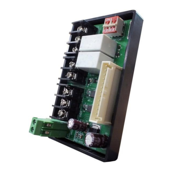
Page 5: About The H2Air
1. About the H Navien H Air is an add-on controller for the Navien water heaters. It adds input and output functions to the water heaters for a combination application where space heating and domestic hot water (DHW) are supplied simultaneously. With... -
Page 6: Specifications
1.2 Specifications Refer to the following table for product specifications. Items Specifications KDO-A100 Model name Add-on controller for Navien water heaters Device type Snap-on Installation type (onto the water heater PCB tray) Main connector socket to water heater Main control connector (13-pin cable) -
Page 7: Wiring Connection Table
1.3.1 Wiring Connection Table Terminal Wiring Connection AHU W1 Connect to AHU W1 AHU W2 Connect to AHU W2 AHU R Connect to AHU R Flow switch Flow switch input terminal T/S W1 Connect to thermostat W1 T/S W2 Connect to thermostat W2 T/S R Connect to thermostat R Outdoor Sensor... -
Page 8: Installing The Device
2. Installing the Device This section provides information required to install the H Air add-on controller in water heaters. WARNING Ensure that you have turned off the power to the water heater before installing the device. 2.1 Basic Principles The following diagram shows the basic operation of water heaters with the H add-on controller. - Page 9 System Diagram for NPE-A2 System Diagram for NPE-S2 Installing the Device...
- Page 10 An outdoor sensor and a flow switch are supplied with the product. Use 18 AWG cables for thermostat wiring. When using an external pump, connect the pump to the water heater PCB directly using a Navien External Pump Cable (GXXX001319). Installing the Device...
-
Page 11: Installing The Device In Water Heaters
2.2 Installing the Device in Water Heaters Follow the instructions to install the Navien H Air in water heaters. 1. Turn off the power supply to the water heater. 2. Remove the water heater’s front cover by loosening the four screws securing it to the case. - Page 12 4. Install the H Air onto the water heater’s PCB tray. Align the latch at the back of the case with the front lip of the PCB tray. 5. Align the two latches at the back of the H Air with the two catch bars at the back of the water heater’s PCB tray.
- Page 13 For NPN: Remove the screws holding the front panel to the bracket to pull out the part. Attach the H Air controller on the back side of the Front Panel at the designated mounting location by using the provided tabs on the component housing.
-
Page 14: Wiring The Device
3. Wiring the Device This section provides information required to plan and install the system wiring. 3.1 System Wiring Examples Refer to the following wiring diagrams to properly install wiring for various setups you may need in your system. Set DIP switch (SW) #3 as specified for each configuration. -
Page 15: 1-Stage Thermostat / 1-Stage Control Heating System
3.1.2 1-Stage Thermostat / 1-Stage Control Heating System Set DIP switch (SW) #3 to ‘Off’ to configure the system to use a 1-stage thermostat / 1-stage control. 3.1.3 2-Stage Thermostat / 2-Stage Control Heating System Set DIP switch (SW) #3 to ‘On’ to configure the system to use a 2-stage thermostat / 2-stage control. -
Page 16: Configuring The Cooling System (For A Heating / Cooling Combo System)
3.1.4 Configuring the Cooling System (for a Heating / Cooling Combo System) To configure the cooling system, connect the thermostat Y terminal to the AHU cooling input terminal Y, and connect the thermostat R terminal to the AHU R output. Wiring the Device... -
Page 17: Cable Connections
Follow the instructions below to connect the cables to the H Air. 3.2.1 Connecting the Outdoor Temperature Sensor Cable An outdoor temperature sensor is supplied with the Navien H Air installation kit. Insert the exposed wire into the terminal. Then tighten the terminal screw with a screwdriver. -
Page 18: Connecting The Thermostat Cables
3.2.2 Connecting the Thermostat Cables The H Air receives input signals from thermostats to control the AHU. Insert the wiring or connector into the contact. Then tighten the terminal screw with a screwdriver. 3.2.3 Connecting the Flow Switch Cables Insert the fork connectors into the contact. Then tighten the terminal screw with a screwdriver. -
Page 19: Connecting The Main Control Connector
3.2.4 Connecting the Main Control Connector To connect the H Air to the Navien water heaters, use the 13-pin main control connector supplied with the Navien H Air. Connect one end of the cable to the connector socket on the H Air PCB. -
Page 20: Configuring The Device
4. Configuring the Device This section provides the information required to set the desired options for the Navien water heater system with the H Air add-on controller. 4.1 System Air Removal Make sure to remove all excess air from the combination system piping. To assist with this process, the NPE and NPE-A2/S2 Series water heater models have an available TEST MODE feature (see below). - Page 21 NPE-A2 System with the Internal or Optional External Pump Set the 2-way valve inside the water heater to ‘EXT’. NPE-S2/NPN System with an External Pump Configuring the Device...
- Page 22 Use 18 AWG wires for thermostat installation. Install certified mixing valves and expansion tanks ONLY. When using an external pump, connect the pump to the water heater PCB directly using a Navien External Pump Cable (GXXX001319). Configuring the Device...
-
Page 23: Dhw Priority Options
4.3 DHW Priority Options Refer to the following options to configure the system’s DHW supply modes. 4.3.1 DHW Priority Mode When the system is configured for the DHW priority mode, space heating does not operate if there is DHW demand (the flow switch is ‘closed’). Set the DIP switch (SW) #2 to ‘Off’... -
Page 24: Parameter Table
5. Parameter Table 5.1 NPE-A and NPN Parameter Table The following table lists the parameters used to configure the water heater system functions. For more information about the parameter settings, refer to the NPE-A or NPN Installation Manual. No. Mode Display Pump Exercise Operation Time Burn Delay Time... -
Page 25: Npe-A2/S2 Parameter Table
5.2 NPE-A2/S2 Parameter Table The following table lists the parameters used to configure the water heater system function. For more information about the parameter settings, refer to the NPE-A2/S2 Installation Manual. 5.2.1 Parameter Settings 1. From the Installer Menu, select 2. Parameter Settings. 2. -
Page 26: Application Settings
5.2.2 Application Settings 1. From the Installer Menu, select 3. Application Settings. 2. After entering the application setting screen, select 3. Air handler Unit, and then press the Up button ( ) or the Down button ( ) to switch between the parameters or to increase or decrease setting values. - Page 27 6. Maintenance The Navien water heaters that are used in the DHW/heating systems should be properly maintained and flushed on an annual basis. Please see the Navien Water Heater Installation Manual for more details regarding annual servicing and maintenance. Maintenance...
- Page 28 7. Appendix Pump P-Q Curve Note When the system uses the internal circulation pump with the NPE-A and NPE-A2 water heaters, the flow rate may vary depending on the type and capacity of the AHU in use. NPE-A and NPE-A2 Pressure Loss Appendix...
- Page 29 NPE-150S2 Pressure Loss NPN Pressure Loss Appendix...
- Page 30 The date of original installation must be provided to Navien, and upon request, proof of the original installation date must also be provided to Navien. When the product is installed in a new construction, the commencement date shall be dated upon which the end-user takes title to the property.
- Page 31 Warranty Exclusions Navien’s Limited Warranty shall be void in the event of an occurrence of any of the following: Improper installation, failure to install in strict compliance with the Installation Manual procedures, installed by a non-licensed installer, and installation in violation of applicable rules, laws or building codes.
- Page 32 Contact the technician or professional who installed your zone pump controller. Contact a licensed professional for the affected system (for example, a plumber or electrician). Version: 1.7 (Feb. 2021) Navien, Inc. 20 Goodyear lrvine, CA 92618 TEL 1-800-519-8794 FAX 1-949-420-0430 www.navieninc.com...
Need help?
Do you have a question about the H2Air and is the answer not in the manual?
Questions and answers