Table of Contents
Advertisement
Quick Links
Advertisement
Table of Contents

Subscribe to Our Youtube Channel
Summary of Contents for Electro Industries/GaugeTech ProtoCom
- Page 1 V.1.04 September 16, 2021...
- Page 2 This page intentionally left blank.
- Page 3 Electro Industries/GaugeTech. © 2021 Electro Industries/GaugeTech Shark®, Nexus®, CommunicatorPQA®, and MeterManagerPQA® are registered trademarks of Electro Industries/GaugeTech. The distinctive shapes, styles, and over- all appearances of all Shark® and Nexus® devices are trademarks of Electro Indus- tries/GaugeTech. V-Switch are trademarks of Electro Industries/GaugeTech.
- Page 4 This page intentionally left blank. Electro Industries/GaugeTech ™ E204701 Powered by Innovation™...
-
Page 5: Customer Service And Support
IMPLIED, GIVEN BY ELECTRO IN CONNECTION WITH THE PRODUCT, AND ELECTRO DISCLAIMS ALL OTHER WARRANTIES, INCLUDING BUT NOT LMITED TO WARRANTIES OF MERCHANTABILITY, FITNESS FOR A PARTICULAR PURPOSE, NON-INFRINGEMENT OF THIRD-PARTY RIGHTS AND WARRANTIES AGAINST LATENT DEFECTS. The Cus- Electro Industries/GaugeTech ™ E204701 Powered by Innovation™... - Page 6 LIMITIED WARRANTY SET FORTH ABOVE FAILS OF ITS ESSENTIAL PURPOSE. EXCEPT AS EXPRESSLY PROVIDED IN THIS SECTION, ELECTRO HEREBY DISCLAIMS AND CUSTOMER WAIVES ALL REPRESENTATIONS, CONDITIONS AND WARRANTIES (WHETHER EXPRESS, IMPLIED, OR STATUTORY), INCLUDING, WITHOUT LIMITATION, Electro Industries/GaugeTech ™ E204701 Powered by Innovation™...
- Page 7 ANY KIND OR NATURE SHALL BE LIMITED TO CUSTOMER'S PURCHASE PRICE FOR THE PRODUCT LICENSED BY THE CUSTOMER FROM ELECTRO, WHICH GAVE RISE TO SUCH CLAIM, WITHOUT REGARD TO ANY ACTUAL DAMAGES; INDIRECT, SPECIAL, Electro Industries/GaugeTech ™ E204701 Powered by Innovation™...
-
Page 8: Use Of Product For Protection
Statement of Calibration Our instruments are inspected and tested in accordance with specifications published by Electro Industries/GaugeTech. The accuracy and a calibration of our instruments are traceable to the National Institute of Standards and Technology through equip- ment that is calibrated at planned intervals by comparison to certified standards. For... -
Page 9: Safety Symbols
• Comply with local electrical code • Be suited to the expected operating temperature range • Meet the current and voltage rating for the ProtoCom/ProtoCom-Lon • Furthermore, the interconnecting power cable shall: • Be of length not exceeding 3.05m (118.3") Electro Industries/GaugeTech ™... -
Page 10: Our Focus At Electro Industries/Gaugetech (Eig)
• This device must not be connected to a LAN segment with outdoor wiring. Our Focus at Electro Industries/GaugeTech (EIG) EIG exclusively delivers integrated energy and power quality monitoring solutions uti- lizing AI and deep industry expertise to improve reliability, efficiency, and sustainabil- ity. -
Page 11: Table Of Contents
1.3: Specifications 1-3 1.4: ProtoCom/ProtoCom-Lon Dimensions 1-4 1.5: Electrical Connections 1-5 1.6: Use of DIP Switches 1-7 1.7: Removing the Top Cover from the ProtoCom/ProtoCom-Lon (ONLY if Necessary) 1-8 1.7.1: Replacing the Top Cover 1-11 1.8: Web Configurator 1-11 1.9: ProtoCom/ProtoCom-Lon Installation 1-13 1.9.1: Mounting on a DIN Rail 1-13... - Page 12 1.10: Navigating This Manual 1-15 2: Using the ProtoCom/ProtoCom-Lon 2-1 2.1: Step One - Configure Modbus Communication Settings 2-1 2.2: Step Two - Select the Desired Field BAS Protocol (ProtoCom only) 2-3 2.3: Step Three - Enable Auto-discovery 2-4 2.4: Step Four - Set MAC Address/Device Instance/Node-ID (Proto- Com only)/IP Address 2-5 2.4.1: Set MAC Address - for BACnet MS/TP Protocol Only 2-5...
- Page 13 2.10.1: Use the Web Configurator to Configure IP Address for BACnet IP and EtherNet/IP 2-17 2.10.2: Set Up a Password 2-21 2.10.3: Configure the ProtoCom-Lon 2-23 2.10.4: Configure the Ethernet Device Connection 2-25 3: Troubleshooting 3-1 3.1: LED Diagnostics for Modbus RTU Communications Between ProtoCom/ProtoCom-Lon and Devices 3-1 3.1.1: No Communication on Modbus RTU (Meter) Side 3-2...
- Page 14 Table of Contents B: MAC Address DIP Switch Settings B-1 C: Validating the ProtoCom in the Field (BACnet MS/TP or BACnet/IP) C-1 C.1: Download the CAS Explorer and Request an Activation Key C-1 C.2: CAS BACnet Setup C-3 C.2.1: CAS BACnet MS/TP Setup C-3 C.2.2: CAS BACnet/IP Setup C-6...
-
Page 15: 1: Introduction To The Protocom/Protocom-Lon
N2, EtherNet/IP and DF1, and Modbus® TCP protocols; and the ProtoCom-Lon sup- ports the LonWorks® protocol. With the ProtoCom, the meters’ Modbus communica- tion is converted into BACnet or other popular BAS protocols. With the ProtoCom-Lon, the meters’ Modbus communication is converted into LonWorks® protocol. -
Page 16: Eig Devices And Available Point Count
1: Introduction to the ProtoCom/ProtoCom-Lon 1.2: EIG Devices and Available Point Count The total number of devices attached to ProtoCom cannot exceed 1500 Modbus registers for BACnet MS/TP, BACnet/IP, Modbus/TCP, Metasys N2, EtherNet/IP, or DF1. The total number of devices attached to ProtoCom-Lon cannot exceed 1000 Modbus registers for LonWorks. -
Page 17: Specifications
1: Introduction to the ProtoCom/ProtoCom-Lon 1.3: Specifications ProtoCom ProtoCom‐Lon One 6‐pin Phoenix connector, one RS485 +/‐ One 6‐pin Phoenix connector, one RS485 +/‐ ground port, power +/‐ frame ground port Electrical ground port, power +/‐ frame ground port One 3‐pin RS485 Phoenix connector, one Connections One Ethernet 10/100 BaseT port RS485 +/‐ ground port One FTT‐10 LonWorks port One Ethernet‐10/100 Ethernet port CE Certified; UL 916 approved; WEEE compliant; EN 60950‐1, EN 50491‐3 and CSA C22‐2 Approvals: standards; FCC Class A Part 15; DNP3 conformance tested; RoHS Compliant; CSA 205 Approved; BTL Marked; LonMark Certified Power Multi‐mode power adapter: (9‐30) V DC or (12 ‐ 24) V AC Requirements Physical 11.5 cm L x 8.3 cm W x 4.1 cm H (4.5 x 3.2 x 1.6 in.) Dimensions Weight: 0.2 kg (0.4 lbs) Operating ‐40 °C to +75 °C (‐40 °F to +167 °F) Temperature: ... -
Page 18: Protocom/Protocom-Lon Dimensions
1: Introduction to the ProtoCom/ProtoCom-Lon 1.4: ProtoCom/ProtoCom-Lon Dimensions Figure 1.2: ProtoCom Dimensions in inches[cm] Electro Industries/GaugeTech ™ E204701 Powered by Innovation™... -
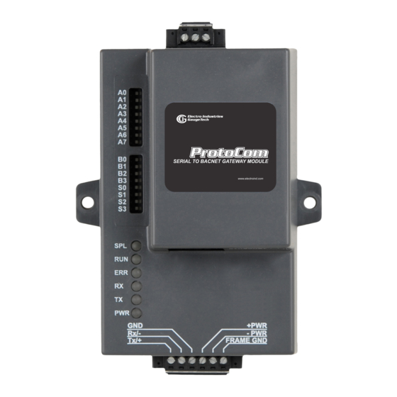
Page 19: Electrical Connections
1: Introduction to the ProtoCom/ProtoCom-Lon 1.5: Electrical Connections Figure 1.3: ProtoCom Electrical Connections Electro Industries/GaugeTech ™ E204701 Powered by Innovation™... - Page 20 1: Introduction to the ProtoCom/ProtoCom-Lon Figure 1.4: ProtoCom-Lon Electrical Connections Electro Industries/GaugeTech ™ E204701 Powered by Innovation™...
-
Page 21: Use Of Dip Switches
The ProtoCom/ProtoCom-Lon makes use of DIP Switches for many of its settings. There are 3 banks of DIP Switches on the ProtoCom/ProtoCom-Lon, but on the ProtoCom-Lon the S bank of DIP Switches is disabled, as it is not used. See the figure below. -
Page 22: Removing The Top Cover From The Protocom/Protocom-Lon (Only If Necessary)
Recommended Procedure to remove the top cover: Using a flat-sided screw driver or similar tool, gently insert it into the 4 slots in the back of the ProtoCom/ProtoCom-Lon, alternating between slots until the cover is loos- ened enough to be removed. Refer to the diagram below. - Page 23 .25”. 4. Keeping the back of the ProtoCom facing you, turn the unit so that the 6 pin connector (labeled HOST) is at the top. Once again, press outward with your Electro Industries/GaugeTech ™...
- Page 24 1: Introduction to the ProtoCom/ProtoCom-Lon thumbs as shown in the diagram below and pull the HOST connector toward you. The main part of the ProtoCom/ProtoCom-Lon will be freed from the top cover. HOST Connector 2.Put right thumb here 1.Put left thumb here 3.Pull outward slightly...
-
Page 25: 1: Replacing The Top Cover
Node Offset or change the IP address (see Section 2.10.1), or to set up a password for the ProtoCom/ProtoCom-Lon (see Section 2.10.2). You can also use it to find devices that are not auto-discoverable, like the PQMII. - Page 26 Enter to open the Web Configurator. You will see the screen shown below. NOTES: • The example screen above is for a ProtoCom running BACnet MS/TP. The screen will look a bit different if you are running another protocol. Electro Industries/GaugeTech ™...
-
Page 27: Protocom/Protocom-Lon Installation
1: Introduction to the ProtoCom/ProtoCom-Lon • If the IP address of the ProtoCom has been changed by previous configuration, you will need to get the assigned IP address from the network administrator. 1.9: ProtoCom/ProtoCom-Lon Installation You have two choices for installing the ProtoCom/ProtoCom-Lon: •... -
Page 28: 2: Mounting On A Panel
3. Unhook the clip from the top of the DIN Rail. 1.9.2: Mounting on a Panel The ProtoCom/ProtoCom-Lon has mounting holes in its tabs for installation in a panel. Mounting Holes Figure 1.12: Location of Mounting Holes 1. Using a #1 flat-blade screwdriver, unscrew the two screws holding the DIN Rail clip to the back of the ProtoCom/ProtoCom-Lom (see Figure 1.11) and remove the clip. -
Page 29: Navigating This Manual
1: Introduction to the ProtoCom/ProtoCom-Lon 1.10: Navigating This Manual Chapter 2 explains how to use the ProtoCom/ProtoCom-Lon with EIG meters, including configuration and wiring. Chapter 3 contains information on device communication. Appendix A contains the EIG meters points list for the supported protocols. - Page 30 1: Introduction to the ProtoCom/ProtoCom-Lon This page intentionally left blank. Electro Industries/GaugeTech ™ E204701 1-16 Powered by Innovation™...
-
Page 31: 2: Using The Protocom/Protocom-Lon
Com/ProtoCom-Lon and an EIG meter. 2.1: Step One - Configure Modbus Communication Settings The ProtoCom/ProtoCom-Lon is designed to connect to either the RS485 Modbus port or the RJ45 Ethernet port of an EIG power meter and to convert the serial or Ethernet communication to the desired protocol. - Page 32 Data Bits Stop Bits 1. Assign a Modbus Address to each of the devices attached to the ProtoCom/Proto- Com-Lon. The Modbus Address needs to be uniquely assigned between 1 and 255. 2. Record the Modbus Address assigned to each device.
-
Page 33: Step Two - Select The Desired Field Bas Protocol (Protocom Only)
Modbus/TCP, Metasys N2, EtherNet/IP, or DF1 (refer to Section 1.6 for an explanation of the DIP switches). Note that the ProtoCom’s default setting enables BACnet, so you don’t need to change this setting unless you want to use another protocol. -
Page 34: Step Three - Enable Auto-Discovery
Auto‐Discovery Settings Auto‐Discovery ON ‐ Build New Configuration Auto‐Discovery OFF ‐ Save Current Configuration When installing the ProtoCom for the first time, set S3 to the ON position to enable Auto-discovery. The ON position is when the DIP switches are set closest to the inside of the box. NOTE: Some meters, such as PQMII, may not be auto-discoverable. In this case, you need to set them up using the Web Configurator. -
Page 35: Step Four - Set Mac Address/Device Instance/Node-Id (Proto-Com Only)/Ip Address
ProtoCom. 2.4.1: Set MAC Address - for BACnet MS/TP Protocol Only • Note that only 1 MAC address is set for the ProtoCom, regardless of how many devices are connected to it. -
Page 36: Protocols
2: Using the ProtoCom/ProtoCom-Lon NOTES: • Refer to Appendix C.1 for the MAC address DIP switch chart. • When using Metasys N2, Modbus/TCP, and DF1 the A Bank of DIP switches are disabled and not used. They should be set to the OFF position. -
Page 37: 3: Device Node-Id For Metasys N2, Modbus/Tcp, And Df1
2.4.3: Device Node-ID for Metasys N2, Modbus/TCP, and DF1 Protocols The Modbus Addresses that you assigned to the devices attached to the ProtoCom in Section 2.1 will be the Metasy N2, Modbus TCP, and DF1 Node_ID's for the field protocols. You don’t need to set up any other identification. -
Page 38: 4: Set Ip Address For Ethernet Devices Connected To Protocom
For Ethernet devices being connected to the ProtoCom/ProtoCom-Lon: • Make sure the device’s protocol is set to Modbus TCP/IP. • The device must be on the same IP subnet as the ProtoCom/ProtoCom-Lon and the PC being used to make communication configuration. -
Page 39: Step 5: Set The Baud Rate For Bacnet Ms/Tp And Df1 Protocols
Switches is disabled for Metasys N2 on ProtoCom, since they are not needed. • The B bank of DIP switches is disabled for the ProtoCom-Lon. • The default setting of the ProtoCom is 38400. The following table shows the Baud Rate DIP Switch selection. Baud... -
Page 40: Step 6 - Connect The Protocom/Protocom-Lon To The Meter
For RS485 serial communication, the six pin connector at the bottom of the Proto- Com/ProtoCom-Lon (labeled HOST) is used to connect the ProtoCom to the EIG meter and to the power supply. (See Section 1.5 for detailed information on the ProtoCom/ ProtoCom-Lon’s connections). - Page 41 Figure 2.5: Connecting RS485 between DMMS 425 and ProtoCom/ProtoCom-Lon For Ethernet communication, use an Ethernet cable to connect from the device’s RJ45 port to the RJ45 port on the ProtoCom/ProtoCom-Lon - see Figure 1.10: ProtoCom/ ProtoCom-Lon Ethernet Port, on page 1-11.
-
Page 42: 1: Biasing The Modbus Rs485 Network (Only If Necessary)
ProtoCom. Refer to Section 1.8 for instructions on removing and replacing the unit’s top cover. The ProtoCom has 510 Ohm resistors that can be used to set the biasing. The default position of the Biasing jumpers is OFF. The OFF position is when the 2 RED biasing jumpers straddle the 4 pins closest to the outside of the board of the ProtoCom. -
Page 43: (Only If Necessary)
1.8 for instructions on removing and replacing the unit’s top cover. If the ProtoCom is placed at one of the ends of the trunk on a long RS485 cabling run, turn the Blue RS485 End-of- Line Terminating switch to the ON position. -
Page 44: Step 7 - Connect To The Rs485/Lonworks Network
Figure 2.8: FIELD RS485 Wiring NOTE: The RS485 GND (Pin 3) is not typically connected. If the ProtoCom is the last device on the BACnet MS/TP, Metasys N2, or DF1 trunk, the End-Of-Line Termination (EOL) Switch needs to be enabled. See Section 1.8 for instructions on removing and replacing the unit’s top cover. -
Page 45: Step 8 - Connect Power To The Protocom/Protocom-Lon
2: Using the ProtoCom/ProtoCom-Lon ProtoCom-Lon: Wire the Field Port to the LonWorks Network Connect the ProtoCom-Lon to the field network with the LonWorks terminal using a twisted pair non-shielded cable. LonWorks has no polarity. Figure 2.10: LonWorks FIELD Terminal 2.8: Step 8 - Connect Power to the ProtoCom/ProtoCom-Lon... -
Page 46: Step 9 - Turn Off Auto-Discovery After Completion To Save Configuration
The S3 DIP Switch for enabling Auto-discovery was set in step 3, Section 2.3. Once power is applied to a ProtoCom/ProtoCom-Lon that is set to enable Auto-discovery, the unit takes about 3 minutes to complete the discovery of all of the EIG meters attached to the ProtoCom/ProtoCom-Lon and the loading of their data points. -
Page 47: Step 10: Additional Configuration
2: Using the ProtoCom/ProtoCom-Lon 2.10: Step 10: Additional Configuration Depending on the protocol being used and the specific needs of your application, you may use the following configuration instructions. 2.10.1: Use the Web Configurator to Configure IP Address for BACnet IP and EtherNet/IP Follow the instructions in 1.8: Web Configurator, on page... - Page 48 2: Using the ProtoCom/ProtoCom-Lon Set the IP Address for Field Network (BACnet/IP, Modbus TCP, and Ethernet/IP Only): 1. From the Web Configurator page, click the Diagnostics & Debugging button in the bottom right side of the page. Click this button...
- Page 49 2. Under Navigation, on the left side of the screen, click Setup>Network Settings. 3. The current network settings are shown in the screen. Enter new IP address here 4. Modify the IP address (N1 IP address field) of the ProtoCom’s Ethernet port. Electro Industries/GaugeTech ™ E204701 2-19...
- Page 50 7. Reset the ProtoCom by clicking the System Restart button at the bottom of the page. 8. Unplug the Ethernet cable from the PC and connect it to the network hub or router. 9. Record the IP address you assigned to the ProtoCom and store it in a safe place. Electro Industries/GaugeTech ™...
-
Page 51: 2: Set Up A Password
• User: the User account can view any ProtoCom/ProtoCom-Lon information, but cannot make any changes to settings or restart the unit. 1. Type the IP address of the ProtoCom/ProtoCom-Lon into your PC’s browser. Click this button 2. From the Web Configurator landing page, click the Diagnostics & Debugging button on the bottom right side of the page to access the FST Web Configurator. - Page 52 2: Using the ProtoCom/ProtoCom-Lon 3. From the navigation tree on the left side of the page, click Setup>Passwords. 4. From the pull-down menu, select Admin or User to set the password for that account. Electro Industries/GaugeTech ™ E204701 2-22 Powered by Innovation™...
-
Page 53: 3: Configure The Protocom-Lon
LonWorks Network Management Tool. Figure 2.12: Location of ProtoCom-Lon Service Pin Instructions Upload an XIF File from the ProtoCom-Lon Using the Using the Web Configurator You may need an XIF file. If so, first follow the instructions in Section 1.9 to connect to the ProtoCom-Lon via its Ethernet port. - Page 54 2: Using the ProtoCom/ProtoCom-Lon For example: 192.168.1.24/fserver.xif If the web browser prompts you to save the file, save it to the PC. If the web browser displays the xif file as a web page (see the example shown below), right-click in the page and save the file to your PC as fserver.xif.
-
Page 55: 4: Configure The Ethernet Device Connection
2: Using the ProtoCom/ProtoCom-Lon 2.10.4: Configure the Ethernet Device Connection Follow the instructions in 1.8: Web Configurator, on page 1-11, to connect to the Pro- toCom via its Ethernet port and to bring up the Web Configurator. 1. Click the Diagnostics & Debugging button at the bottom of the webpage. - Page 56 2: Using the ProtoCom/ProtoCom-Lon 3. Make these Network settings: • Modify the IP Address (N1 IP Address field) of the ProtoCom’s Ethernet port. • If necessary, change the Netmask (N1 Netmask field). • If necessary, change the IP Gateway (Default Gateway field).
-
Page 57: 3: Troubleshooting
3.1: LED Diagnostics for Modbus RTU Communications Between ProtoCom/ProtoCom-Lon and Devices The ProtoCom/ProtoCom-Lon has LEDs that indicate communication between the device and both the EIG meters and other devices it is connected to. The LEDs can be used to diagnose communication problems.The diagram below shows the unit’s LED Locations. -
Page 58: 1: No Communication On Modbus Rtu (Meter) Side
If the TX/RX LEDs are not flashing rapidly, there is a communication problem on the Modbus (Meter) side. Check the following items: • The action of the ProtoCom/ProtoCom-Lon LEDs - see the table on the previous page. • The baud rate, parity, data bits, and stop bits are set correctly •... -
Page 59: Lost Or Incorrect Ip Address
2. Unzip and install the FieldServer Toolbox application. 3. Connect a standard Cat-5 Ethernet cable between the PC and the ProtoCom. 4. Open the FieldServer Toolbox application from the Start menu and click Discover Now on the splash page. - Page 60 6. If you need to correct the gateway’s IP address, click the Settings icon on the same row as the gateway, click Network Settings, change the IP Address, and then click Update IP Settings to save the new address. Electro Industries/GaugeTech ™ E204701 3 - 4 Powered by Innovation™...
-
Page 61: Clearing Profiles
3: Troubleshooting 3.3: Clearing Profiles If you need to start the ProtoCom installation over, you can clear existing device pro- files. Follow these instructions: 1. Follow the instructions in 1.8: Web Configurator, on page 1-11, to connect to the ProtoCom via its Ethernet port and to bring up the Web Configurator. - Page 62 3: Troubleshooting This page intentionally left blank. Electro Industries/GaugeTech ™ E204701 3 - 6 Powered by Innovation™...
-
Page 63: A: Protocol Data Points For Eig Meters
A: Protocol Data Points for EIG Meters A: Protocol Data Points for EIG Meters Lists of the protocol data points for the supported EIG meters begins on the next page. Electro Industries/GaugeTech ™ Doc# E204701 Powered by Innovation™... -
Page 64: A.1: Shark® 100 Meter
Negative VARs 3 Ph Avg Flt_XXX[18] F10:18 nvoNgVAR3PhA_XXX SNVT_count_inc_f VAs 3 Ph Avg Flt_XXX[19] F10:19 nvoVA3Ph_Avg_XXX SNVT_count_inc_f Positive PF 3 Ph Avg Flt_XXX[20] F10:20 nvoPsPF3PhAv_XXX SNVT_count_inc_f Negative PF 3 PF Avg Flt_XXX[21] F10:21 nvoNgPF3PhAv_XXX SNVT_count_inc_f Electro Industries/GaugeTech ™ Doc# E204701 Powered by Innovation™... - Page 65 Serial Number Reg 7 Dev_XXX[18] N12:18 nvoSerNum7_XXX SNVT_count Serial Number Reg 8 Dev_XXX[19] N12:19 nvoSerNum8_XXX SNVT_count Password for Reset in use Byt_XXX[5] N13:5 nvoPswdReset_XXX SNVT_count Password for Configuration in use Byt_XXX[6] N13:6 nvoPswdCnfg_XXX SNVT_count Electro Industries/GaugeTech ™ Doc# E204701 Powered by Innovation™...
-
Page 66: A.2: Shark® 200 Meter
S32_XXX[1] F11:1 nvoWh_Del_XXX SNVT_count_inc_f W hours Net S32_XXX[2] F11:2 nvoWh_Net_XXX SNVT_count_inc_f W hours Total S32_XXX[3] F11:3 nvoWh_Tot_XXX SNVT_count_inc_f VAR hours Positive S32_XXX[4] F11:4 nvoVARh_Pos_XXX SNVT_count_inc_f VAR hours Negative S32_XXX[5] F11:5 nvoVARh_Neg_XXX SNVT_count_inc_f Electro Industries/GaugeTech ™ Doc# E204701 Powered by Innovation™... - Page 67 Serial Number Reg 3 Dev2_XXX[6] N13:6 nvoSerNum3_XXX SNVT_count Serial Number Reg 4 Dev2_XXX[7] N13:7 nvoSerNum4_XXX SNVT_count Serial Number Reg 5 Dev2_XXX[8] N13:8 nvoSerNum5_XXX SNVT_count Serial Number Reg 6 Dev2_XXX[9] N13:9 nvoSerNum6_XXX SNVT_count Electro Industries/GaugeTech ™ Doc# E204701 Powered by Innovation™...
- Page 68 Serial Number Reg 7 Dev2_XXX[1 N13:10 nvoSerNum7_XXX SNVT_count Serial Number Reg 8 Dev2_XXX[1 N13:11 nvoSerNum8_XXX SNVT_count Password for Reset in use Byt_XXX[5] N14:5 nvoPswdReset_XXX SNVT_count Password for Configuration in use Byt_XXX[6] N14:6 nvoPswdCnfg_XXX SNVT_count Electro Industries/GaugeTech ™ Doc# E204701 Powered by Innovation™...
-
Page 69: A.3: Nexus® 1252/1262/1272 Meters
SNVT_count_inc_f Max Block Window Avg Pos VAR S32_XXX[19] F10:19 nvoMBWAvPVAR_XXX SNVT_count_inc_f Max Block Window Avg Neg VAR S32_XXX[20] F10:20 nvoMBWAvNVAR_XXX SNVT_count_inc_f Max Block Window Avg Pos Watt S32_XXX[21] F10:21 nvoMBWAvPWat_XXX SNVT_count_inc_f Electro Industries/GaugeTech ™ Doc# E204701 Powered by Innovation™... - Page 70 System Hookup Dev3_XXX[0] N14:0 nvoSysHookup_XXX SNVT_count Password State Dev3_XXX[1] N14:1 nvoPass_Stat_XXX SNVT_count Comm Device Status Dev3_XXX[2] N14:2 nvoComDevSt_XXX SNVT_count DSP Device Status Dev3_XXX[3] N14:3 nvoDSPDevSt_XXX SNVT_count Serial Number U32_XXX[0] F11:0 nvoSerNum_XXX SNVT_count_inc_f Electro Industries/GaugeTech ™ Doc# E204701 Powered by Innovation™...
-
Page 71: A.4: Dmms 425 Meter
Watt Hour Block 2 Dev_XXX[1] N11:1 nvoWh_Blk2_XXX SNVT_count Watt Hour Block 3 Dev_XXX[2] N11:2 nvoWh_Blk3_XXX SNVT_count Watt Hour Block 4 Dev_XXX[3] N11:3 nvoWh_Blk4_XXX SNVT_count Watt Hour Block 5 Dev_XXX[4] N11:4 nvoWh_Blk5_XXX SNVT_count Electro Industries/GaugeTech ™ Doc# E204701 Powered by Innovation™... -
Page 72: A.5: Nexus® 1500 Meter
Var Hour Block 7 Dev_XXX[14] N11:14 nvoVARh_Blk7_XXX SNVT_count Var Hour Block 8 Dev_XXX[15] N11:15 nvoVARh_Blk8_XXX SNVT_count CT Ratio Dev_XXX[16] N11:16 nvoCT_Ratio_XXX SNVT_count PT Ratio Dev_XXX[17] N11:17 nvoPT_Ratio_XXX SNVT_count A.5: Nexus® 1500 Meter Electro Industries/GaugeTech ™ Doc# E204701 A-10 Powered by Innovation™... - Page 73 SNVT_count_inc_f Max Blk Window Avg VA S32_XXX[19] F10:19 nvoMxBlWdAVA_XXX SNVT_count_inc_f Max Blk Window Avg Pos VAR S32_XXX[20] F10:20 nvoMBWdAPVAR_XXX SNVT_count_inc_f Max Blk Window Avg Neg VAR S32_XXX[21] F10:21 nvoMBWdANVAR_XXX SNVT_count_inc_f Electro Industries/GaugeTech ™ Doc# E204701 A-11 Powered by Innovation™...
-
Page 74: A.6: Mp200-Y Metering System
N15:5 nvoSerNum1_XXX SNVT_count Serial Number Reg 2 Dev3_XXX[6] N15:6 nvoSerNum2_XXX SNVT_count Serial Number Reg 3 Dev3_XXX[7] N15:7 nvoSerNum3_XXX SNVT_count Serial Number Reg 4 Dev3_XXX[8] N15:8 nvoSerNum4_XXX SNVT_count A.6: MP200-Y Metering System Electro Industries/GaugeTech ™ Doc# E204701 A-12 Powered by Innovation™... - Page 75 MTR03 Power Factor 3 Ph total Flt_XXX[029] F10:029 nvoM3PFTot_XXX SNVT_count_inc_f MTR03 Neutral Current Flt_XXX[030] F10:030 nvoM3NeutCur_XXX SNVT_count_inc_f MTR04 Amps A Flt_XXX[031] F10:031 nvoM4AmpsA_XXX SNVT_count_inc_f MTR04 Amps B Flt_XXX[032] F10:032 nvoM4AmpsB_XXX SNVT_count_inc_f Electro Industries/GaugeTech ™ Doc# E204701 A-13 Powered by Innovation™...
- Page 76 MTR08 Amps B Flt_XXX[064] F10:064 nvoM8AmpsB_XXX SNVT_count_inc_f MTR08 Amps C Flt_XXX[065] F10:065 nvoM8AmpsC_XXX SNVT_count_inc_f MTR08 Watts 3 Ph total Flt_XXX[066] F10:066 nvoM8WattTot_XXX SNVT_count_inc_f MTR08 VARs 3 Ph total Flt_XXX[067] F10:067 nvoM8VARsTot_XXX SNVT_count_inc_f Electro Industries/GaugeTech ™ Doc# E204701 A-14 Powered by Innovation™...
- Page 77 MTR04 W hours Delivered S32_XXX[028] F11:028 nvoM4WHDel_XXX SNVT_count_inc_f MTR04 W hours Net S32_XXX[029] F11:029 nvoM4WHNet_XXX SNVT_count_inc_f MTR04 W hours Total S32_XXX[030] F11:030 nvoM4WHTot_XXX SNVT_count_inc_f MTR04 VAR hours Positive S32_XXX[031] F11:031 nvoM4VARHPos_XXX SNVT_count_inc_f Electro Industries/GaugeTech ™ Doc# E204701 A-15 Powered by Innovation™...
-
Page 78: A.7: Mp200-S Metering System
MTR08 W hours Received S32_XXX[063] F11:063 nvoM8WHRec_XXX SNVT_count_inc_f MTR08 W hours Delivered S32_XXX[064] F11:064 nvoM8WHDel_XXX SNVT_count_inc_f MTR08 W hours Net S32_XXX[065] F11:065 nvoM8WHNet_XXX SNVT_count_inc_f MTR08 W hours Total S32_XXX[066] F11:066 nvoM8WHTot_XXX SNVT_count_inc_f Electro Industries/GaugeTech ™ Doc# E204701 A-16 Powered by Innovation™... - Page 79 SNVT_count_inc_f MTR06 Negative Watts 3 Ph Avg Flt_XXX[098] F10:098 nvoM6NgWtAvg_XXX SNVT_count_inc_f MTR06 Negative VARs 3 Ph Avg Flt_XXX[099] F10:099 nvoM6NgVARAv_XXX SNVT_count_inc_f MTR06 VAs 3 Ph Avg Flt_XXX[100] F10:100 nvoM6VAsAvg_XXX SNVT_count_inc_f Electro Industries/GaugeTech ™ Doc# E204701 A-17 Powered by Innovation™...
- Page 80 MTR05 Negative Watts 3 Ph Max Avg Dem Flt_XXX[129] F10:129 nvo5NWtMxAvD_XXX SNVT_count_inc_f MTR05 Negative VARs 3 Ph Max Avg Dem Flt_XXX[130] F10:130 nvo5NVARMxAv_XXX SNVT_count_inc_f MTR06 Positive Watts 3 Ph Max Avg Dem Flt_XXX[131] F10:131 nvo6PWtMxAvD_XXX SNVT_count_inc_f Electro Industries/GaugeTech ™ Doc# E204701 A-18 Powered by Innovation™...
- Page 81 SNVT_count_inc PT denominator Dev2_XXX[018] N13:018 nvoPT_den_XXX SNVT_count_inc System Hookup Dev2_XXX[019] N13:019 nvoSysHookup_XXX SNVT_count_inc Password for Reset in use Byt_XXX[0] N14:0 nvoPswdReset_XXX SNVT_count_inc Password for Configuration in use Byt_XXX[1] N14:1 nvoPswdCnfg_XXX SNVT_count_inc Electro Industries/GaugeTech ™ Doc# E204701 A-19 Powered by Innovation™...
- Page 82 Power Factor Meter 04 Flt_XXX[029] F10:029 nvoPFM4_XXX SNVT_count_inc_f Power Factor Meter 05 Flt_XXX[030] F10:030 nvoPFM5_XXX SNVT_count_inc_f Power Factor Meter 06 Flt_XXX[031] F10:031 nvoPFM6_XXX SNVT_count_inc_f Amps Meter 07 Flt_XXX[032] F10:032 nvoAmpsM7_XXX SNVT_count_inc_f Electro Industries/GaugeTech ™ Doc# E204701 A-20 Powered by Innovation™...
- Page 83 F10:063 nvoAmpsM14_XXX SNVT_count_inc_f Amps Meter 15 Flt_XXX[064] F10:064 nvoAmpsM15_XXX SNVT_count_inc_f Watts Meter 13 Flt_XXX[065] F10:065 nvoWattsM13_XXX SNVT_count_inc_f Watts Meter 14 Flt_XXX[066] F10:066 nvoWattsM14_XXX SNVT_count_inc_f Watts Meter 15 Flt_XXX[067] F10:067 nvoWattsM15_XXX SNVT_count_inc_f Electro Industries/GaugeTech ™ Doc# E204701 A-21 Powered by Innovation™...
- Page 84 F10:098 nvoVARsM19_XXX SNVT_count_inc_f VARs Meter 20 Flt_XXX[099] F10:099 nvoVARsM20_XXX SNVT_count_inc_f VARs Meter 21 Flt_XXX[100] F10:100 nvoVARsM21_XXX SNVT_count_inc_f VAs Meter 19 Flt_XXX[101] F10:101 nvoVAsM19_XXX SNVT_count_inc_f VAs Meter 20 Flt_XXX[102] F10:102 nvoVAsM20_XXX SNVT_count_inc_f Electro Industries/GaugeTech ™ Doc# E204701 A-22 Powered by Innovation™...
- Page 85 S32_XXX[012] F12:012 nvoVARhPosM1_XXX SNVT_count_inc_f VAR hours Positive Meter 02 S32_XXX[013] F12:013 nvoVARhPosM2_XXX SNVT_count_inc_f VAR hours Positive Meter 03 S32_XXX[014] F12:014 nvoVARhPosM3_XXX SNVT_count_inc_f VAR hours Negative Meter 01 S32_XXX[015] F12:015 nvoVARhNegM1_XXX SNVT_count_inc_f Electro Industries/GaugeTech ™ Doc# E204701 A-23 Powered by Innovation™...
- Page 86 S32_XXX[047] F12:047 nvoVARhNetM6_XXX SNVT_count_inc_f VAR hours Total Meter 04 S32_XXX[048] F12:048 nvoVARhTotM4_XXX SNVT_count_inc_f VAR hours Total Meter 05 S32_XXX[049] F12:049 nvoVARhTotM5_XXX SNVT_count_inc_f VAR hours Total Meter 06 S32_XXX[050] F12:050 nvoVARhTotM6_XXX SNVT_count_inc_f Electro Industries/GaugeTech ™ Doc# E204701 A-24 Powered by Innovation™...
- Page 87 S32_XXX[082] F12:082 nvoWHRecM11_XXX SNVT_count_inc_f W hours Received Meter 12 S32_XXX[083] F12:083 nvoWHRecM12_XXX SNVT_count_inc_f W hours Delivered Meter 10 S32_XXX[084] F12:084 nvoWHDelM10_XXX SNVT_count_inc_f W hours Delivered Meter 11 S32_XXX[085] F12:085 nvoWHDelM11_XXX SNVT_count_inc_f Electro Industries/GaugeTech ™ Doc# E204701 A-25 Powered by Innovation™...
- Page 88 S32_XXX[117] F12:117 nvoWHTotM13_XXX SNVT_count_inc_f W hours Total Meter 14 S32_XXX[118] F12:118 nvoWHTotM14_XXX SNVT_count_inc_f W hours Total Meter 15 S32_XXX[119] F12:119 nvoWHTotM15_XXX SNVT_count_inc_f VAR hours Positive Meter 13 S32_XXX[120] F12:120 nvoVARhPsM13_XXX SNVT_count_inc_f Electro Industries/GaugeTech ™ Doc# E204701 A-26 Powered by Innovation™...
- Page 89 S32_XXX[152] F12:152 nvoVARhNgM18_XXX SNVT_count_inc_f VAR hours Net Meter 16 S32_XXX[153] F12:153 nvoVARhNtM16_XXX SNVT_count_inc_f VAR hours Net Meter 17 S32_XXX[154] F12:154 nvoVARhNtM17_XXX SNVT_count_inc_f VAR hours Net Meter 18 S32_XXX[155] F12:155 nvoVARhNtM18_XXX SNVT_count_inc_f Electro Industries/GaugeTech ™ Doc# E204701 A-27 Powered by Innovation™...
- Page 90 S32_XXX[187] F12:187 nvoVAhTotM20_XXX SNVT_count_inc_f VA hours Total Meter 21 S32_XXX[188] F12:188 nvoVAhTotM21_XXX SNVT_count_inc_f W hours Received Meter 22 S32_XXX[189] F12:189 nvoWHRecM22_XXX SNVT_count_inc_f W hours Received Meter 23 S32_XXX[190] F12:190 nvoWHRecM23_XXX SNVT_count_inc_f Electro Industries/GaugeTech ™ Doc# E204701 A-28 Powered by Innovation™...
- Page 91 Flt_XXX[128] F10:128 nvoNgWtM1Avg_XXX SNVT_count_inc_f Negative Watts Meter 02 Avg Flt_XXX[129] F10:129 nvoNgWtM2Avg_XXX SNVT_count_inc_f Negative Watts Meter 03 Avg Flt_XXX[130] F10:130 nvoNgWtM3Avg_XXX SNVT_count_inc_f Negative VARs Meter 01 Avg Flt_XXX[131] F10:131 nvoNgVARM1Av_XXX SNVT_count_inc_f Electro Industries/GaugeTech ™ Doc# E204701 A-29 Powered by Innovation™...
- Page 92 Flt_XXX[163] F10:163 nvoPsVAR12Av_XXX SNVT_count_inc_f Negative Watts Meter 10 Avg Flt_XXX[164] F10:164 nvoNgWtM10Av_XXX SNVT_count_inc_f Negative Watts Meter 11 Avg Flt_XXX[165] F10:165 nvoNgWtM11Av_XXX SNVT_count_inc_f Negative Watts Meter 12 Avg Flt_XXX[166] F10:166 nvoNgWtM12Av_XXX SNVT_count_inc_f Electro Industries/GaugeTech ™ Doc# E204701 A-30 Powered by Innovation™...
- Page 93 Flt_XXX[198] F10:198 nvoPsVAR20Av_XXX SNVT_count_inc_f Positive VARs Meter 21 Avg Flt_XXX[199] F10:199 nvoPsVAR21Av_XXX SNVT_count_inc_f Negative Watts Meter 19 Avg Flt_XXX[200] F10:200 nvoNgWtM19Av_XXX SNVT_count_inc_f Negative Watts Meter 20 Avg Flt_XXX[201] F10:201 nvoNgWtM20Av_XXX SNVT_count_inc_f Electro Industries/GaugeTech ™ Doc# E204701 A-31 Powered by Innovation™...
- Page 94 Pos Watts Meter 05 Max Avg Dem Flt_XXX[231] F10:231 nvoPWt5MxAvD_XXX SNVT_count_inc_f Pos Watts Meter 06 Max Avg Dem Flt_XXX[232] F10:232 nvoPWt6MxAvD_XXX SNVT_count_inc_f Pos VARs Meter 04 Max Avg Dem Flt_XXX[233] F10:233 nvoPVAR4MxAv_XXX SNVT_count_inc_f Electro Industries/GaugeTech ™ Doc# E204701 A-32 Powered by Innovation™...
- Page 95 Pos Watts Meter 13 Max Avg Dem Flt_XXX[266] F11:011 nvoPWt13MxAv_XXX SNVT_count_inc_f Pos Watts Meter 14 Max Avg Dem Flt_XXX[267] F11:012 nvoPWt14MxAv_XXX SNVT_count_inc_f Pos Watts Meter 15 Max Avg Dem Flt_XXX[268] F11:013 nvoPWt15MxAv_XXX SNVT_count_inc_f Electro Industries/GaugeTech ™ Doc# E204701 A-33 Powered by Innovation™...
- Page 96 Neg VARs Meter 21 Max Avg Dem Flt_XXX[301] F11:046 nvoNVAR21MxA_XXX SNVT_count_inc_f Pos Watts Meter 22 Max Avg Dem Flt_XXX[302] F11:047 nvoPWt22MxAv_XXX SNVT_count_inc_f Pos Watts Meter 23 Max Avg Dem Flt_XXX[303] F11:048 nvoPWt23MxAv_XXX SNVT_count_inc_f Electro Industries/GaugeTech ™ Doc# E204701 A-34 Powered by Innovation™...
- Page 97 CT Numerator Meter 21 Dev2_XXX[021] N14:021 nvoCTNum21_XXX SNVT_count_inc CT Numerator Meter 22 Dev2_XXX[022] N14:022 nvoCTNum22_XXX SNVT_count_inc CT Numerator Meter 23 Dev2_XXX[023] N14:023 nvoCTNum23_XXX SNVT_count_inc CT Numerator Meter 24 Dev2_XXX[024] N14:024 nvoCTNum24_XXX SNVT_count_inc Electro Industries/GaugeTech ™ Doc# E204701 A-35 Powered by Innovation™...
- Page 98 Serial Number Reg 7 Dev3_XXX[008] N15:008 nvoSerNum7_XXX SNVT_count_inc Serial Number Reg 8 Dev3_XXX[009] N15:009 nvoSerNum8_XXX SNVT_count_inc Password for Reset in use Byt_XXX[0] N16:0 nvoPswdReset_XXX SNVT_count_inc Password for Configuration in use Byt_XXX[1] N16:1 nvoPswdCnfg_XXX SNVT_count_inc Electro Industries/GaugeTech ™ Doc# E204701 A-36 Powered by Innovation™...
-
Page 99: A.8: Shark® 250/270 Meter
F10:26 Flt_XXX[026] nvoPF_PhC_XXX SNVT_count_inc_f W hours Received 28 AI F11:0 Scl_XXX[000] nvoWh_Rec_XXX SNVT_count_inc_f F11:1 W hours Delivered 29 AI Scl_XXX[001] nvoWh_Del_XXX SNVT_count_inc_f F11:2 W hours Net 30 AI Scl_XXX[002] nvoWh_Net_XXX SNVT_count_inc_f Electro Industries/GaugeTech ™ Doc# E204701 A-37 Powered by Innovation™... - Page 100 SNVT_count_inc_f Negative VARs 3 Ph Max Avg Demand 54 AI F10:40 Flt_XXX[040] nvoNVr3PMADm_XXX SNVT_count_inc_f CT Denominator 55 AI N13:0 Dev_XXX[104] nvoCT_den_XXX SNVT_count N13:1 CT Numerator 56 AI Dev_XXX[105] nvoCT_num_XXX SNVT_count Electro Industries/GaugeTech ™ Doc# E204701 A-38 Powered by Innovation™...
- Page 101 SNVT_count Serial Number Reg 6 65 AI N14:6 Dev_XXX[115] nvoSerNum6_XXX SNVT_count N14:7 Serial Number Reg 7 66 AI Dev_XXX[116] nvoSerNum7_XXX SNVT_count N14:8 Serial Number Reg 8 67 AI Dev_XXX[117] nvoSerNum8_XXX SNVT_count Electro Industries/GaugeTech ™ Doc# E204701 A-39 Powered by Innovation™...
-
Page 102: A.9: Pqmii Meter
C Phase Real Power S32_XXX[026] F11:26 nvoCPhRlPwr_XXX SNVT_count_inc_f C Phase Reactive Power S32_XXX[027] F11:27 nvoCPhRacPwr_XXX SNVT_count_inc_f C Phase Apparent Power S32_XXX[028] F11:28 nvoCPhAppPwr_XXX SNVT_count_inc_f C Phase Power Factor S16_XXX[019] N10:19 nvoCPhPF_XXX SNVT_count_inc_f Electro Industries/GaugeTech ™ Doc# E204701 A-40 Powered by Innovation™... - Page 103 Serial Number Reg 2 Dev_XXX[089] N12:5 nvoSerNum2_XXX SNVT_count_inc_f Serial Number Reg 3 Dev_XXX[090] N12:6 nvoSerNum3_XXX SNVT_count_inc_f Serial Number Reg 4 Dev_XXX[091] N12:7 nvoSerNum4_XXX SNVT_count_inc_f 3 Phase Real Power Max Demand S32_XXX[029] F11:29 nvo3PhRlPMxD_XXX SNVT_count_inc_f Electro Industries/GaugeTech ™ Doc# E204701 A-41 Powered by Innovation™...
- Page 104 Type Address EIP Tag Name Address Lon Name Lon SNVT Type 3 Phase React Power Max Demand S32_XXX[030] F11:30 nvo3PhRcPMxD_XXX SNVT_count_inc_f 3 Phase Apparent Power Max Demand S32_XXX[031] F11:31 nvo3PhApPMxD_XXX SNVT_count_inc_f Electro Industries/GaugeTech ™ Doc# E204701 A-42 Powered by Innovation™...
-
Page 105: B: Mac Address Dip Switch Settings
B: MAC Address DIP Switch Settings B: MAC Address DIP Switch Settings This following table lists the settings for the A Bank of DIP switches, used to set a MAC address. Address Electro Industries/GaugeTech ™ E204701 B - 1 Powered by Innovation™... - Page 106 B: MAC Address DIP Switch Settings Address Electro Industries/GaugeTech ™ E204701 B - 2 Powered by Innovation™...
- Page 107 B: MAC Address DIP Switch Settings Address Electro Industries/GaugeTech ™ E204701 B - 3 Powered by Innovation™...
- Page 108 B: MAC Address DIP Switch Settings Address Electro Industries/GaugeTech ™ E204701 B - 4 Powered by Innovation™...
- Page 109 B: MAC Address DIP Switch Settings Address Electro Industries/GaugeTech ™ E204701 B - 5 Powered by Innovation™...
- Page 110 B: MAC Address DIP Switch Settings Address Electro Industries/GaugeTech ™ E204701 B - 6 Powered by Innovation™...
-
Page 111: C: Validating The Protocom In The Field (Bacnet Ms/Tp Or Bacnet/Ip
C: Validating the ProtoCom in the Field C: Validating the ProtoCom in the Field (BACnet MS/TP or BACnet/IP) There are free software applications that can be used to validate BACnet MS/TP and/ or BACnet/IP communications in the field, without having to have the BMS Integrator on site. - Page 112 C: Validating the ProtoCom in the Field 4. Once you receive the email with the activation key, go to http://www.chipkin.com/ technical-resources/cas-bacnet-explorer/. 5.. Scroll down until you see the Download icon. 6. Click Executable (dmb) and run the file. A Setup Wizard will step you through downloading the CAS Bacnet Explorer application.
-
Page 113: C.2: Cas Bacnet Setup
10. Click the Activate button to begin your two week free trial. C.2: CAS BACnet Setup Following is an example of how to configure the ProtoCom with a BACnet Explorer. The one shown here was developed by Chipkin Automation Systems. It is subject to all of their licenses and restrictions. - Page 114 C: Validating the ProtoCom in the Field 2. Open the CAS BACnet Explorer application to display the main screen. 3. Click on Settings. 4. In the Networks section, check the BACnet MSTP box and uncheck the BACnet/IP and BACnet Ethernet boxes.
- Page 115 C: Validating the ProtoCom in the Field 5. Set the BACnet MSTP MAC address to 0. 6. Set the BACnet MSTP Baud Rate to 38400. 7. Click OK. 3. In the bottom right-hand corner of the main screen, make sure that the BACnet MSTP box is green.
-
Page 116: C.2.2: Cas Bacnet/Ip Setup
1-11, to set the IP address and subnet of the PC that will be running the CAS BACnet Explorer. 2. Connect a straight or crossover Ethernet cable from the PC to the ProtoCom. 3. Open the CAS BACnet Explorer application to display the main screen. - Page 117 C: Validating the ProtoCom in the Field 4. Click on Settings. 5. In the Networks section, check the BACnet/IP box and uncheck the BACnet MSTP and BACnet Ethernet boxes. 6. In the Select a Network Device box, select the PC’s network card by clicking on it.
- Page 118 C: Validating the ProtoCom in the Field 7. Click OK. 4. In the bottom right-hand corner of the screen, make sure that the BACnet/IP box is green. 5. Click on Discover. 6. Check all 4 boxes. 7. Click Send. The screen will display BACnet network information.
Need help?
Do you have a question about the ProtoCom and is the answer not in the manual?
Questions and answers