
Related Manuals for Com-Power ACS-230-25W


Summary of Contents for Com-Power ACS-230-25W
- Page 1 COM-POWER INSTRUCTION MANUAL For the ACS-230-25W 150 kHz to 230 MHz 25W Power Amplifier Page 1 of 15 MANUAL_ACS-230-25W Rev. M02.15 Distributed by: Reliant EMC LLC, +1 408 916‐5750, info@reliantemc.com, www.reliantemc.com...
-
Page 2: Table Of Contents
Table of Contents Important Safety Precautions.…………………………...…………………………3 Introduction.………………………………………………………………………….5 Product Specifications ……………….……………………………………………...6 Front/Rear Panel……………………...…...…………………………………………8 Amplifier Operation...…..……….…...……………………..……………..…….…10 Page 2 of 15 MANUAL_ACS-230-25W Rev. M02.15 Distributed by: Reliant EMC LLC, +1 408 916‐5750, info@reliantemc.com, www.reliantemc.com... -
Page 3: Important Safety Precautions
Important Safety Precautions Safety Symbol Guide ATTENTION Refer Manual WARNING High Voltage Do not attempt to disassemble the instrument. Please contact our service department. AC power input should be within the voltage range specified on the rear panel. Please ensure that the correct fuse is installed prior to applying power for the first time. - Page 4 Do not exceed +3 dBm into the RF INPUT. Do not place heavy objects on top of the instrument. Avoid any rough handling that could damage the ACS-250-25W unit. Use electrostatic discharge precautions while handling and making connections to the ACS-250-25W unit.
-
Page 5: Introduction
Introduction Com-Power model ACS-230-25W series broadband amplifiers operate from 150 kHz to 230 MHz. This amplifier can be used for EMI immunity testing that requires generating electric fields. This small and lightweight amplifier utilizes class AB linear power devices that provide high gain, and wide dynamic range. -
Page 6: Product Specifications
Product Specifications:- Frequency Range … 150 kHz - 230 MHz Power Output: Rated Output … 25 watts into 2:1 VSWR Power Protection Limit … 30 watts Limit@ 1dB compression … 40 watts Gain … 44dB ± 2 dB Input for rated output …... - Page 7 Display and Interfaces … USB Remote Interface Front panel display … Continuous monitoring and display of Temperature, Current, Input / Output Power, VSWR and Gain Mechanical: Cooling Requirement … Forced air (self contained fans) Size … 19” Rack 2U Weight …...
-
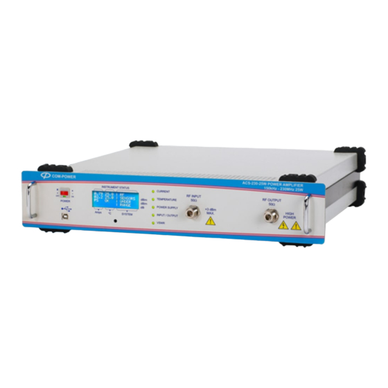
Page 8: Front/Rear Panel
Front/Rear Panel Front Panel: 1. RF ON/OFF Switch 2. Indicates Power is ON when Green Light is lit 3. LCD Display 4. Fault Indicators 5. USB Interface- for remote sensing and external data controls. 6. RF Input Port- make the connections required for the 50 Ohm system before turning on the unit. - Page 9 9. Handles Rear Panel: Mains power input to unit with inbuilt fuse socket. The power input can be between 100V AC to 250VAC,47-63Hz, 400VA. The unit auto detects the power supply voltage. The fuse provides primary AC circuit protection. In case of failure of Fuse, replace only with the rated fuse {5x 20 mm 250 V, 5A, (T)} 11.
-
Page 10: Amplifier Operation
Amplifier Operation 1. Before turning on the unit, make sure the RF Input and Output connectors on the front panel are terminated with 50 Ohms system. 2. Turn on power from rear panel. Following message will display on LCD. Page 10 of 15 MANUAL_ACS-230-25W Rev. - Page 11 In normal condition following message will be displayed NOTE: Prior to turning the Front panel power switch ON, Please ensure that the RF output of the RF signal source connected to the Amplifier input is turned off or below -45dBm. When the unit turns on the ACS-230-50W system starts a self test.
- Page 12 3. Turn on Switch from the front panel as shown in picture. Upon successful completion of self test mode, LCD screen will display the Driver 1& 2 Current/Temperature, Module Current/Temperature and System Status. Please note that Pin, Pout, SWR and Gain will not be displayed until the amplifier sees an input of -45dBm.
- Page 13 Displays with its meaning: Driver1 Driver1 Current/Temperature (Line 1, columns 1/2 on LCD) Driver2 Driver2 Current/Temperature (Line 2, columns 1/2 on LCD) Module Current/Temperature (Line 2, columns 1/2 on LCD) Power Supply status (Line 3 on LCD) Prev Reflected Power sensed at the RF output (Line 1, column 3 on LCD) Input Power to the unit (Line 2, column 3 on LCD) Pout...
- Page 14 7. Depending on the nature of the fault the appropriate red LED will be light up and the corresponding fault message will be displayed on front panel LCD. 8. In order to restart the unit, first turn off the front panel switch, and then restart the unit as described in Section 3.
- Page 15 9. Please refer below Diagnostics chart to check fault conditions FAULT MESSAGE ON FAULT POSSIBLE CAUSE SR.#. LIGHT LIT LCD SCREEN PA CURRENT RANGE Power limit was exceeded EXCEEDED Indicates that the current * Mismatch on 50-ohm through the module exceeds Current System DRIVER...
Need help?
Do you have a question about the ACS-230-25W and is the answer not in the manual?
Questions and answers