Table of Contents

Related Manuals for Com-Power PAP-501


Summary of Contents for Com-Power PAP-501
- Page 1 Page 1 of 9 INSTRUCTION MANUAL Preamplifier Model PAP‐501 INSTRUCTION MANUAL For Preamplifier Model PAP‐501 10 MHz to 1000 MHz, 21 dB Gain 19121 El Toro Rd ● Silverado, CA 92676 ● (949) 459‐9600● fax (949) 635‐0329 ● com‐power.com REV21516 ...
-
Page 2: Table Of Contents
Page 2 of 9 INSTRUCTION MANUAL Preamplifier Model PAP‐501 Table of Contents Introduction ...................... 3 2. 0 Product Specifications .................... 4 2.1 Other related equipment available from Com‐Power. .......... 4 2.2 Other RF and Microwave preamplifier models available from Com‐Power .... 4 3. 0 Important Precautions .................... 5 3.1 Excessive RF input ...................... 5 Saturation........................ 5 3.2 3.3 Calibration ........................ 5 4.0 ... -
Page 3: Introduction
Page 3 of 9 INSTRUCTION MANUAL Preamplifier Model PAP‐501 1.0 Introduction This manual includes product specifications, safety precautions, product maintenance and warranty information. Information contained in this manual is the property of Com‐Power Corporation. It is issued with the understanding that none of the material may be reproduced or copied without permission from Com‐Power. 19121 El Toro Rd ● Silverado, CA 92676 ● (949) 459‐9600● fax (949) 635‐0329 ● com‐power.com REV21516 ... -
Page 4: Product Specifications
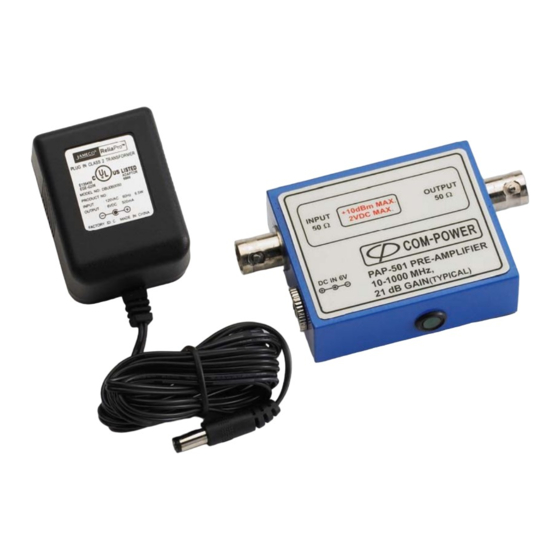
Page 4 of 9 INSTRUCTION MANUAL Preamplifier Model PAP‐501 2. 0 Product Specifications Model: PAP‐501 Electrical Frequency Range: 10 MHz to 1000 MHz Minimum Gain: 21 dB Flatness: + 2 dB Max input: +10 dBm, 2 VDC at 1 dB compression point: +10 dBm Noise Figure: 3.5 dB Impedance (Input/Output): 50Ω Connector types: BNC (f) 6 VDC, 500 mA / 115 VAC, 60 Hz ( 230VAC,50 Power adapter (Output /Input): HZ) Power adapter plug size: 2.5 x 5.5 mm 10 ˚ C to 40 ˚ C Operating Temperature: Mechanical Dimensions L x W x H: ... -
Page 5: Important Precautions
Page 5 of 9 INSTRUCTION MANUAL Preamplifier Model PAP‐501 3. 0 Important Precautions Observe the following safety precautions to ensure user safety and maximizing the operating life of the preamplifier. • Use only the power adapter supplied with the preamplifier. • Exercise caution when handling the preamplifier because it is sensitive electrostatic discharge. • Avoid using the preamplifier in environments with excessive heat or moisture. There are no other user serviceable parts inside the unit. Do not remove the main instrument cover. If the preamplifier needs repair please contact authorized Com‐Power service center. 3.1 Excessive RF input Do not exceed RF input level indicated on front panel. Excessive RF input may damage the preamplifier’s sensitive input and will not be covered under warranty. 3.2 Saturation In addition possible damage to the preamplifier input, excessive RF signals may cause the preamplifier to saturate. When a preamplifier reaches saturation point the gain will reduce and cause a nonlinear increase in output power resulting inaccurate measurements. PAP‐501 can handle up to +10 dBm (117 dBµV) input signal. 3.3 Calibration The factory recommended calibration period for the Preamplifier is 12 months. However, its performance should be checked periodically to ensure the preamplifier is operating within the rated specification given in section 2.0 of this manual. 19121 El Toro Rd ● Silverado, CA 92676 ● (949) 459‐9600● fax (949) 635‐0329 ● com‐power.com REV21516 ... -
Page 6: Warranty
Page 6 of 9 INSTRUCTION MANUAL Preamplifier Model PAP‐501 4.0 Warranty Com‐Power warrants to its Customers that the products it manufactures will be free from defects in materials and workmanship for a period of 3 years. This warranty shall not apply to: • Transport damages during shipment from your plant. • Damages due to poor packaging. • Products operated outside their specifications. • Products Improperly maintained or modified. • Consumable items such as fuses, power cords, cables, etc. • Normal wear • Calibration • Products shipped outside the United States without the prior knowlege of Com‐ Power. ... -
Page 7: Application And Product Operation
Page 7 of 9 INSTRUCTION MANUAL Preamplifier Model PAP‐501 5.0 Application and product operation 5.1 Application Com‐Power PAP‐501 Preamplifer are designed specifically for EMI radiated emissions testing up to 1 GHz. The PAP‐501 high gain of the preamplifier • Amplifies signals within its operational frequency band to improve the overall signal noise ratio of the measurement system. • Compensates for signal losses associated with the use of cables and antennas operating within its frequency range. ... -
Page 8: Troubleshooting Common Problems
Page 8 of 9 INSTRUCTION MANUAL Preamplifier Model PAP‐501 5.4 Troubleshooting Common problems Problem: Gain is low or no gain. A: Make sure the power adapter is plugged in and the green is LED is lit. Check if the input and output cables are connected securely. Wiggle both cables and verify if the signal level changes on the receiver. If the signal changes replace the defective cable and check again. Make sure the cable from the signal source is connected to the input not the output. Verify if the signal source connected and RF is turned on. If the signal source is an antenna or near field probes make sure they are properly connected. Inject a known signal level into the preamplifier and check the gain. For example if you inject 50 dBµV, you should read ~ 71 to 73 dBµV on the receiver. Please be cautious not to exceed the input limits given in specification table of this manual. ... -
Page 9: Typical Preamplifier Gain
Page 9 of 9 INSTRUCTION MANUAL Preamplifier Model PAP‐501 6.0 Typical Preamplifier Gain 1000 Frequency (MHz) 19121 El Toro Rd ● Silverado, CA 92676 ● (949) 459‐9600● fax (949) 635‐0329 ● com‐power.com REV21516 ...
Need help?
Do you have a question about the PAP-501 and is the answer not in the manual?
Questions and answers