
Related Manuals for Shire Rose Arbour


Summary of Contents for Shire Rose Arbour
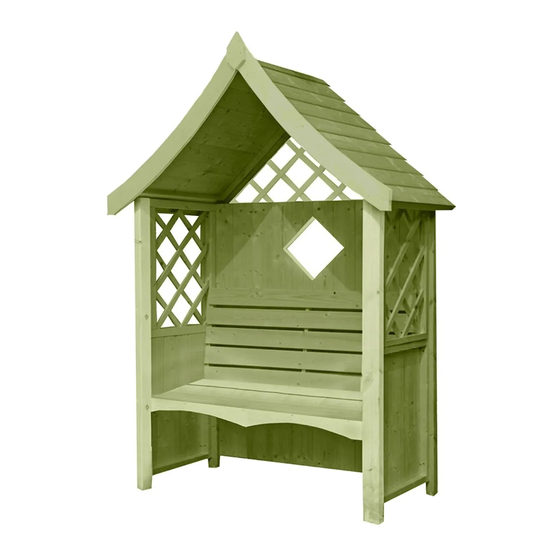
- Page 1 Mass: 56.1 kg © Rose Arbour These instructions are for your safety. Please read through them thoroughly before use. PLEASE KEEP THIS LEAFLET FOR FUTURE REFERENCE...
-
Page 2: Table Of Contents
Let’s get started... Important information... Safety Preparation of base Warranty Care, maintenance & Recycling In more detail... Parts List Fascia & Nail List Detailed Technical Drawing 08-09 Hardware Chart Before you start Assembly Instructions 12-27 For a copy of the instructions or a copy in another language please send an email or write to the address below. -
Page 3: Safety
Safety Check that you have noted all the following instructions: We advise the use of non slip protective gloves throughout the assembly process. We advise the use of steel capped protective footwear throughout the assembly process. We advise that you use a helper to hold the glass in position whilst you nail the beading in place. -
Page 4: Preparation Of Base
Base and Warranty Preparation of base... We recommend that the base onto which your building will stand should be at least 75mm larger in each direction than the total floor size of the building. Actual floor area of the building: 1236mm x 654mm ... -
Page 5: Care, Maintenance & Recycling
Care, Maintenance and Recycling The 5 golden rules of care: Ensure your base is level and firm. Ensure the building is not sitting directly on the ground using damp proof membrane or the optional timber base. Ensure every piece of timber and surface, especially that is hidden upon assembly, is treated with a top quality wood preservative at least twice (before assembly). -
Page 6: Parts List
Stacked Parts List Description (part No ) - Qty... -
Page 7: Fascia & Nail List
Stacked and Nail Bag Parts List Description (part No ) - Qty... -
Page 10: Hardware Chart
Nail bag contents Description (part No ) - Qty Hardware Chart Scale 1:1 40mm Round Head Nail (A0025) x 14 25mm Posi-Drive Screw (A0032) x 03 40mm Posi-Drive Screw (A0033) x 13 60mm Posi-Drive Screw (A0035) x 45 Building Photographs It will be greatly appreciated if you could forward images of your... -
Page 11: Before You Start
Before you start... Things to check before you start: Ensure your base is ready – See page 4. Check all parts as listed in the parts lists. Read the instructions fully before starting work. Follow all the health and safety guidelines. When you see the drill icon Only ever drill through the first piece of framework which will be a... -
Page 12: Assembly Instructions
Assembly instructions: These instructions are for your safety. Please read through them thoroughly before use. Treat all the parts before assembly – see page 5! The “Panel layout” is showing you how to position the panels. GB-IE The Panels FIT INBETWEEN THE CORNER POSTS! A5910 A5921 A5921... - Page 13 Lay the Large Window Panel (A5910) flat. GB-IE Screw two Corner Posts (A5921) to the sides as below, using 6x 60mm Screws (A0035) and the pilot holes drilled in the previous step. Step 1 (A5910)x01 Flat edge sits flush with outside cladding. Corner Post (A5921)x02 60mm Screws...
- Page 14 Drill one Window Panel (A5911) as below. Drill top holes at an angle. Making sure the GB-IE outside cladding is facing inwards and flush with the flat face of the corner post, fix with 3x 60mm Screws (A0035) using the pilot holes previously drilled. Then screw another Corner Post (A5921) as below, using the pilot holes.
- Page 15 Drill the other Window Panel (A5911) as below, making sure the cladding is facing inwards. GB-IE Then fix the last Corner Post (A5921) so that the flat face is flush with the cladding on the Side Panel. Use 6x 60mm Screws (A0035). 5 mm Sits flush with post Window Panel...
- Page 16 Lay the building flat. GB-IE Drill two holes as below in each of the 34x34x590 (A5923). Measure and mark from the bottom of the Window Panel up 368mm. Make sure the top of the frame sits flush at the 368mm mark. Fix both with 40mm Screws (A0033). 34x34x590 (A5923)x02 40mm Screws...
- Page 17 Drill the 34x34x1052 (A5922) as below. GB-IE Screw the frame to the Large Window Panel so that the top is flush with the frames screwed in Step 5. Fix with 40mm Screws (A0033). 34x34x1052 (A5922)x01 40mm Screws (A0033)x05 View from above...
- Page 18 Pre-Drill through the bottom of the seat frame bars as below. DO NOT DRILL THROUGH GB-IE THE SEAT BASE. Place the Seat Base (A5912) onto the seat frame built in Steps 5+6. Screw from underneath the seat with 60mm Screws (A0035) using the pilot holes. Seat Base (A5912)x01 60mm Screws...
- Page 19 Place the RH Seat Back (A5889) onto the Seat Base as below. Drill and screw through the GB-IE Window Panel so the screws go into the side bar of the Seat Backing. Measure and mark on the Large Window Panel where the middle bar of the seat back sits. Then drill and screw using 2x 60mm Screws (A0035).
- Page 20 Drill the Outer Trellis (A5916) as below. Drill two holes along the 1160mm edge. GB-IE Place the Inner Trellis (A5915) inside the Outer Trellis so that the back framework of both Trellises are flush. (Hatching is facing inwards). Screw together with 40mm Screws (A0033) using the pilot holes. Outer Trellis (A5916)x01 Inner Trellis...
- Page 21 Place the Trellis built in Step 9 onto your building as below. Trellis can be placed either way GB-IE around but make sure it is flush with the cladding on the Large Window Panel. Measure and make sure it sits equally either side. Fix with 60mm Screws (A0035) using the pilot holes. Step 09 60mm Screws (A0035)x02...
- Page 22 GB-IE Drill one Roof Panel (A5914) as below. Place the 44x44x722 (A5924) on top of the Roof Panel as below and fix with 3x 60mm Screws (A0035). Roof Panel (A5914)x01 44x44x722 (A5924)x01 60mm Screws (A0035)x03...
- Page 23 Drill the other Roof Panel (A5914) as below. GB-IE Place the panel adjacent to the first as below Fix with 60mm Screws (A0035) to the 44x44x722 bar. Roof Panel (A5914)x01 60mm Screws (A0035)x03...
- Page 24 GB-IE Nail one Roof Capping (A5925) so it sits flush the edge of the 44x44x722 bar as below. Then nail the other Roof Capping (A5925) so it overlaps the other as below. Fix with 40mm Nails (A0025). Roof Capping (A5925)x02 40mm Nails (A0025)x06...
- Page 25 Place the assembled Roof Panels onto your building as below. GB-IE The corner posts should fit in between the Roof Panels. The bar inside the Roof Panel should rest upon the Window Panels. Screw from the outside using 3x 60mm Screws (A0035) in each side as below. 60mm Screws (A0035)x06 Screws go into Side Panels...
- Page 26 GB-IE Fix the Fascia (A5919) to the front of your building as below. Fix with 3x 40mm Nails (A0025) in each. Fix the Diamond (A5913) centrally using 2x 40mm Nails (A0025) as below. Fascia (A5919)x02 Diamond (A5913)x01 40mm Nails (A0025)x08...
- Page 27 GB-IE Drill and screw the Seat Fascia 1120 (A5920) to the seat base framework as below. Fix using 3x 25mm Screws (A0032), spaced evenly apart. Seat Fascia 1120 (A5920)x01 25mm Screws (A0032)x03...
Need help?
Do you have a question about the Rose Arbour and is the answer not in the manual?
Questions and answers