
Related Manuals for Mircom OpenBAS-HV-RF433R

Summary of Contents for Mircom OpenBAS-HV-RF433R
- Page 1 OpenBAS-HV-RF433R Wireless Receiver Installation Manual LT-6634 Rev. 0 February 2018...
-
Page 3: Table Of Contents
Table of Contents Introduction OpenBAS-HV-RF433R Wireless Receiver ..............Features ......................... Overview OpenBAS-HV-RF433R Components ................2.1.1 Controllers ........................Installation Parts of the Enclosure ....................Controller Board Connections ..................Installing Accessories ....................3.3.1 I2C Connector ........................ Enclosure Dimensions ....................Assembly ........................Mounting the Enclosures .................... - Page 4 Fit the circuit board in enclosure ..................Figure 7 Enclosure mounted on DIN rail (circuit board not shown) ..........Figure 8 Enclosure mounted on DIN rail (back view) ..............Figure 9 OpenBAS-HV-RF433R ....................Figure 10 Networking the RF and I2C modules ................Figure 11 LEDs ..........................
- Page 5 List of Tables Table 1 OpenBAS-HV-RF433R Controllers ................
-
Page 6: Introduction
This document provides information on installing the OpenBAS-HV-RF433R Wireless Receiver. OpenBAS-HV-RF433R Wireless Receiver Mircom’s OpenBAS-HV-RF433R Wireless Receiver is a wireless 433 MHz RF receiver that integrates up to 10 wireless transmitters and thermostats into NX series controllers except for OpenBAS-HV-NX4AO. -
Page 7: Overview
Overview OpenBAS-HV-RF433R Components 2.1.1 Controllers Table 1 OpenBAS-HV-RF433R Controllers Picture Model Description RF module I2C module Wireless 433 MHz RF receiver that integrates up to 10 wireless transmitters and thermostats into OpenBAS-HV-RF433R OpenBAS-LC-NX12R and OpenBAS- HV-NX series controllers Mounts in a DIN rail-mounted box... -
Page 8: Installation
Jurisdiction (AHJ). Parts of the Enclosure The OpenBAS-HV-RF433R consists of two modules: the RF module and the I2C module. The RF module receives information wirelessly from the OpenBAS-HV-WLSTH thermostat. The I2C module is connected to any OpenBAS NX controller, or an OpenBAS-NWK-ETH3 controller through the I2C connection. -
Page 9: Figure 2 Tabs On Enclosure
Installation To remove the circuit board from the enclosure Caution: Risk of Electric Shock. Disconnect the mains power and disconnect the controller from all wiring before opening the enclosure. Attention: Always hold circuit boards by the edges to prevent damage from static electricity. -
Page 10: Figure 3 Lift Tabs And Remove Circuit Board
Installation 2. Hold the circuit board with one hand, and with the other hand lift the tabs so that you can remove the circuit board from the enclosure. See Figure 3. Lift tabs and remove circuit board Circuit board Figure 3 Lift tabs and remove circuit board Attention: Be careful not to break the tabs. -
Page 11: Controller Board Connections
Connect the I2C port of the I2C module (shown in Figure 4) to the I2C port of an OpenBAS controller. The maximum length of the connection is 1 foot (30 cm). The OpenBAS-HV-RF433R receives power from the OpenBAS controller that it is connected Note: When connecting the I2C ports on 2 devices, make sure to connect pin 1 on the first device to pin 1 on the second device. -
Page 12: Enclosure Dimensions
Installation Enclosure Dimensions 1 27/64” (36 mm) Hooks 3 35/64” (90 mm) Mounting clip Figure 5 Enclosure (back view) -
Page 13: Assembly
2. Snap the base onto the enclosure. Make sure that the mounting clip is on the bottom. 3. Snap the cover in place. Make sure that the Mircom logo is the right way up. Attention: Always hold circuit boards by the edges to prevent damage from static electricity. -
Page 14: Mounting The Enclosures
Installation Mounting the Enclosures Attention: Mount the RF module on a DIN rail in a UL-compliant plastic box to allow reception of RF signals from the OpenBAS-HV-WLSTH transmitter. Mount the I2C module on a DIN rail in a UL-compliant metal or plastic box. -
Page 15: Figure 8 Enclosure Mounted On Din Rail (Back View)
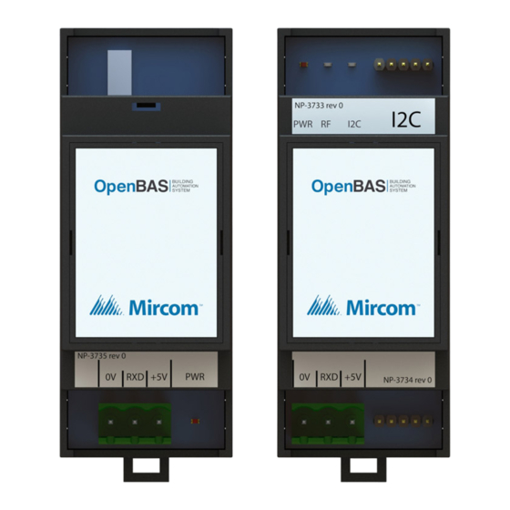
I2C module 0V RXD +5V 0V RXD +5V Figure 9 OpenBAS-HV-RF433R To remove the enclosure from the DIN rail • With your hands or with a small flathead screwdriver, pull the mounting clip to release the enclosure from the DIN rail, and carefully pull the enclosure off the DIN rail. -
Page 16: Field Wiring
Field Wiring Note: Installation of OpenBAS-HV-RF433R automation controllers must be in accordance with the Canadian Electrical Code or the National Electrical Code, and comply with all local regulations. Final acceptance is subject to the Local Authority Having Jurisdiction (AHJ). Wiring the Terminals Figure 4 on page 11 shows the location of the terminals. -
Page 17: Wireless Communication
Field Wiring Wireless Communication See LT-6131 “OpenBAS-HV-WLSTH Installation Manual” for a description of how the OpenBAS-HV-RF433R receives information wirelessly with OpenBAS-HV-WLSTH. Circuit Board LEDs • PWR: Is red when the unit is powered • LINK-RF: Solid green to indicate communication over the wireless link. Flashes green to... -
Page 18: Specifications
Specifications Standards: UL 60730-1 Input: 12 Vdc, 26 mA max., or 24 Vdc, 26 mA max., or 24 Vac 50/60 Hz, 74 mA max. Powered over I2C connector Wireless Characteristics: Frequency: 433 MHz Range: 15 m (49 ft) indoors, 30 m (98 ft) outdoors with line of sight Physical Characteristics: Weight: 360 g (12.8 oz) Enclosure dimensions: 1 27/64”... -
Page 19: Warranty And Warning Information
As the only individual in contact with system users, please bring each item in this warning to the attention of the users of this Mircom System. Failure to properly inform system end-users of the circumstances in which the system might fail may result in over-reliance upon the system. - Page 20 11. Battery Failure. If the Mircom System or any device connected to the system operates from batteries it is possible for the batteries to fail. Even if the batteries have not failed, they must be fully charged, in good condition, and installed correctly.
- Page 21 20. Integrated Products. Mircom System might not function as intended if it is connected to a non-Mircom product or to a Mircom product that is deemed non-compatible with a particular Mircom System.
- Page 22 CANADA - Main Office U.S.A © Mircom 2018 25 Interchange Way 4575 Witmer Industrial Estates Printed in Canada Subject to change without prior notice Vaughan, ON L4K 5W3 Niagara Falls, NY 14305 Tel: (905) 660-4655 Tel: (905) 660-4655 www.mircom.com (888) 660-4655...
Need help?
Do you have a question about the OpenBAS-HV-RF433R and is the answer not in the manual?
Questions and answers