Table of Contents
Advertisement
Quick Links
Advertisement
Table of Contents

Subscribe to Our Youtube Channel
Related Manuals for Turbo EIT Series


Summary of Contents for Turbo EIT Series
- Page 1 TURBO s.r.l. Electronic Control Systems for Dust Collectors e-mail: info@tu rbocontrols.it web: www.turbocontrols.eu TEL. +39 (0)362 574024 FAX +39 (0)362 574092 BUILT-IN ECONOMISER EIT SERIES 1 to 16 solenoid valves User Manual 01/02/2021 Manual Release 1.03 Hardware Release 4.00...
-
Page 2: General Description
General Description The EIT control unit is an electronic device for controlling pneumatic cleaning of the Industrial Dust Collector Systems. The pressure transducer mounted on the unit measures the differential pressure, allowing an accurate analysis of the filter clogging status. The control unit has 2 relay contacts, to signal alarm events, a 4-20mA self-powered output, useful for transmitting the pressure value read to a remote device, and a large graphical LCD, which displays the operating status and, through a membrane keypad, allows... - Page 3 Electrical Features Power Supply: Warning! Read the section on 115Vac ± 10% 50-60 Hz – 25W · installation before connecting the device. 230Vac ± 10% 50-60 Hz – 25W · 24Vac ± 10% 50-60 Hz – 25W (optional) · 24Vdc ± 10% – 25W (optional) ·...
- Page 4 Warning Symbols Used in the Manual The indications regarding safety are highlighted using the following symbols: Attention - Danger Warning - Generic Risk – Hazard Electric Current Dispose of according to the WEEE Waste Electrical and Electronic Equipment Directive Installation Regulations and Warnings Protect the equipment from direct sunlight.
- Page 5 The cable glands must be chosen according to the diameter of the cable to be used. Ü The tightness of the cable gland is guaranteed by the compression of the rubber seal Ü that tightens on the outer diameter of the cable. The size of cable and cable gland must ensure that a power cord traction is not acting on Ü...
-
Page 6: Display And Keyboard
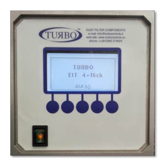
Display and keyboard A 5-key membrane keypad is placed on the front panel. This is useful for accessing control unit functions. At power-on, the Control unit will show the product’s name and the installed firmware version. After the unit is switched on, the information about the operating status will appear on the display, such as the pressure dP reading, the operating mode set, the cycle time and the operating status. - Page 7 Main Menu The menu and the individual functions in the same are organised as follows: Base Settings Default Manual (dP value displayed but not used) Automatic Operating Mode AUTOMATIC Automatic with forced cycle Proportional Solenoid valve activation time Pulse time 0.05 seconds –...
- Page 8 Alarms Default Enabling of the alarm on maintenance interval Al. Maintenance Disabled disabled – enabled Values that can be set Maintenance interval expressed in tens of hours Maint. interval 001 – 999 (step 1). 100 hours Values that can be set: (example: 1=10h, 10=100h) Enabling of the Minimum dP Alarm function Min DP alarm...
- Page 9 Counters Default Overall counter of the hours of activity of the device from Tot.hour count commissioning. Maintenance Hour counter, dependent on the operating Maint.hour CT period of the fan. Overall counter of the pulses of activity of the device from Pulse Tot: commissioning.
- Page 10 Alarms The control unit performs a series of checks during the ignition cycle and normal operation. Below find descriptions of possible alarms and relative solutions: Code Description Operation - If 24Vdc is desired, switch the device off and move Output voltage setting the AC/DC jumpers to DC.
- Page 11 Code Description Operation Short Circuit on one or more outputs Signalling of code E08 alternates with the Switch the device off and back on again, after having verified the connections of the solenoid indication of the output of interest. It is valves.
-
Page 12: Operation Description
Operation Description When the control unit is switched on, the LCD shows the SW version installed, while it verified congruency of the settings memorised in EEprom and the positions of the voltage selection hardware jumpers. Whenever there is a discrepancy between the settings, the corresponding error code will be displayed (Ref. - Page 13 Cleaning Function with Fan Off (PCC) This function allows one or more cleaning cycles to be performed (the number of cycles is “PCC Cycles” defined in ) when the fan is off. The status of the fan can be determined from “Fan Mode= from contact the status of the contacts 12-13 (contacts open = fan off) if ”, or...
- Page 14 Control Board Connection Layout Pressure Sensor dP + pressure input section dirty dP + negative pressure input section clean...
-
Page 15: Input/Output Contacts
Input/Output Contacts Input Terminal Description Used to activate the control unit from remote; it be activated deactivated from a distance. Remote Enabling 14-15 The control unit is supplied with a jumper on Contact terminals 14-15. Without this, switches on but does not perform any activity, in stand-by for the contact to be closed. - Page 16 Terminals Table Terminal Description Terminal Description Input 115-230Vac Relay switch alarm 01 Input 115-230Vac Relay switch alarm 01 PE Protection Earth Relay switch alarm 02 Relay switch alarm 02 Solenoid Valves PE Earth Common Solenoid valve Solenoid valve output 01 Fan Input Solenoid valve output 02 Fan Input...
- Page 17 Power Supply Jumpers Configuration 115 Vac 230 Vac Output Voltages Jumpers Configuration 115 Vac 230 Vac 24 Vac 24 Vdc...
-
Page 18: Installation And Dimensions
Installation and Dimensions Dimensions in mm... -
Page 19: Maintenance
Maintenance Apart from the fuse, the control unit does not have replaceable parts. All other repairs must be carried out by the manufacturer. To clean dust and dirt from the surfaces, rub delicately with cotton or another type of soft cloth soaked in a non-aggressive, non-abrasive detergent. -
Page 20: Troubleshooting
Incorrect Zero dP calibration. self/calibration function, explained in the 0.0 kPa. Operating paragraph. TURBO s.r.l. Electronic Control Systems for Dust Collectors e-mail: info@tu rbocontrols.it web: www.turbocontrols.eu TEL. +39 (0)362 574024 FAX +39 (0)362 574092...
Need help?
Do you have a question about the EIT Series and is the answer not in the manual?
Questions and answers