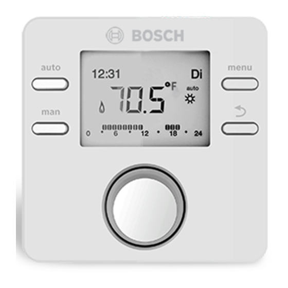
Bosch CRC200 Quick Start Manual
+ outdoor reset (with third-party controls)
Hide thumbs
Also See for CRC200:
- Installation instructions for contractors (32 pages) ,
- User manual (28 pages)
Advertisement
Bosch CRC200 + Outdoor Reset (with Third-Party Controls) Quick Start Guide
The Bosch CRC200 (part number 7738111034) is an optional controller that can
enhance boiler operation when used with third-party controls to manage all zones.
The CRC200 controller is necessary for enabling outdoor temperature reset control; it
replaces the discontinued Bosch FW200 controller.
This guide is intended ONLY for quick start of outdoor reset when used with
a third-party zone/thermostat system.
1
Installation
Make all wiring connections before powering up the boiler. Install the CRC200
controller near the boiler using the included base. Do not mount the CRC200 in the
living space when a non-Bosch thermostat or zone controller is managing all zones.
Manufacturing date code of CRC200 must be 960 (Dec. 2019) or newer.
Control Wiring
The terminal strips vary on wall vs. fl oor models. Wall boiler terminals are inside the
Heatronic control panel; fl oor terminals are in an electrical box on the rear of the
boiler. Refer to fi gures 1 and 2 below.
Terminals "BB" (BUS1) are for Bosch accessories only: CRC200, CZM100,
CT100
Terminals "2 & 4" (TT2) are thermostat/zone box dry contacts dry contacts
for all third-party controls
Terminals "A & F" (Out Sen3) are for the Bosch outdoor temp sensor kit (PN
87472071010)
Figure 1
Greenstar Wall Boiler
Figure 2
Greenstar Floor Boiler
1. Connect the CRC200 to terminals "BB" on the wall boiler (BUS1 on the fl oor
boiler) using 18-2 wire, not longer than 100 ft.
2. Remove the jumper from terminals 2 & 4 (TT2) and connect the third-party
thermostat or zone controller here. Note: The Greenstar will not run if the
jumper is removed and nothing is connected to 2 & 4 (TT2). Terminals 2 & 4
(TT2) take priority over "BB" (BUS1), but they work together to manage the
boiler & zones when using outdoor reset.
3. Connect the outdoor temperature sensor to "A & F" (Out Sen3) on the boiler.
4. Open the temp sensor housing using a screwdriver; pry gently to avoid damage.
Once wired, install it on the north wall of the building, away from all heat sources
& sunlight. The temp sensor must be connected to the boiler or the CRC200 will
not display the outdoor reset menu during setup.
Bosch Thermotechnology Corp.
BTC 465103301 A | 04.2021
Confi guring the CRC200
Figure 3
Press the "back" button
needed).
1. Language selection appears. English (EN) starts fl ashing. Press the dial to
confi rm, or rotate the dial to the desired language and press to confi rm. If the
CRC was already programmed, skip to step 14.
2. Date appears. Turn the dial to set month/day/year, and press dial to accept each
fi eld.
3. Time appears. Turn the dial to set the time (hours/minutes) and then press the
dial to proceed.
4. Heating zone (HC) assignment appears. Press the dial to confi rm the setting of
"HC1".
5. Auto Confi g. appears. Turn the dial and select "Yes". Wait a few seconds while
the CRC200 searches for connected devices. The menu will automatically move
to "DHW" menu when confi guration is fi nished (or directly to LLH menu if it is a
combi boiler).
6. DHW appears (for heat-only boilers; DHW is not displayed on combi models).
Turn dial & select the right choice for your system (Yes, pr. pump, 3-way valve,
no DHW).
7. LLH appears. Select "Yes on Mod." for the included supply temp sensor, or "No"
if no sensor exists.
8. Recirculation appears. Select "No".
9. Heat system appears. Select "low temp" for in-fl oor radiant, "high temp" for
radiators or baseboards.
10. Design temp appears. The defaults shown in the chart below are 113℉ for low
temp and 167℉ for high temp systems. Adjust the set points as needed for your
specifi c application. You will set the correct outside temp for your region later in
this quick-start guide.
CRC Defaults
Outside temperature
Design temperature
Max. supply temperature
Table 1
Part No. 7738111034
to redo the last step or last data entry if
Low Temp.
High Temp.
14 °F
14 °F
113 °F
167 °F
118 °F
167 °F
1
Advertisement
Table of Contents

Related Manuals for Bosch CRC200


Summary of Contents for Bosch CRC200
- Page 1 9. Heat system appears. Select “low temp” for in-fl oor radiant, “high temp” for radiators or baseboards. 1. Connect the CRC200 to terminals “BB” on the wall boiler (BUS1 on the fl oor boiler) using 18-2 wire, not longer than 100 ft.
- Page 2 The CRC200 can also be used with other Bosch NSC controls (CZM100, CRC100) to heating temperature of the boiler. This setting does NOT reduce DHW output for manage up to 8 zones without the need for third-party controls. The CRC200 can be a combi boiler or indirect tank.
Need help?
Do you have a question about the CRC200 and is the answer not in the manual?
Questions and answers