
Related Manuals for Plasma IBEAM FC

Summary of Contents for Plasma IBEAM FC
- Page 1 PLASMA PROCESS GROUP, INC. IBEAM FC / FN Ion Beam Source Power Supply Manual DC Filament Cathode / Filament Neutralizer...
- Page 2 Copyright 2009, 2015 by Plasma Process Group, Inc. All rights reserved 7330 Greendale Road, Windsor, CO 80550 Phone 970-663-6988 • Fax 970-669-2312 No part of this publication may be reproduced without prior written permission Date: May, 2015 v2.0...
-
Page 3: Table Of Contents
T able of Contents Chapter 1: Introduction 1.1: Description 1.2: Limited warranty . 1.3: Service and Technical Contact Information 1.4: Warning Statements Chapter 2: Theory of Operation . 2.1: Source Parameter Definitions . 2.2: Ion Beam Properties . 2.3: References . Chapter 3: Set up and Installation Procedures . -
Page 4: Chapter 1: Introduction
[8-10]. A basic physical knowledge of plasma behavior is required: however, the mathematical descriptions will be kept to a minimum. For any technical assistance, please contact us. We at Plasma Process Group hope that using your new ion beam source will produce rewarding results. -
Page 5: Description
The I-BEAM™ FC/FN Power Supply provides power and control for ion beam sources with filament cathodes and filament neutralizers. Designed especially to optimize performance of Plasma Process Group's 3cm and 8cm ion beam sources, the I-BEAM™ FC/FN can run sources from other manufacturers as well. -
Page 6: Limited Warranty
Section 1.2: Limited Warranty Our workmanship warranty: All equipment manufactured and sold by Plasma Process Group Inc is warranted to be free of defects and workmanship when shipped. The latest copy of our warranty statement can be obtained on our website www.plasmaprocessgroup.com/itemdocs/tech/Terms_and_conditions.pdf... -
Page 7: Service And Technical Contact Information
Section 1.3: Technical Contact Information For Service or Repair contact: Plasma Process Group Inc (PPG) www.plasmaprocessgroup.com Please supply the following information: Product Model and serial number Date Purchased Detailed description of problem Contact person If the product is to be returned to PPG for repair you will be assigned a Return Authorization number (RA), warranty status of the equipment and shipping information to return the product. -
Page 8: Warning Statements
Section 1.4: Warning Statements WARNING This symbol illustrates a voltage hazard. CAUTION This symbol is used to warn of a potential voltage hazard. WARNING This symbol is used to warn of electrocution hazard. WARNING This symbol is used to warn of a HIGH VOLTAGE hazard. Warning –... -
Page 9: Chapter 2: Theory Of Operation
An electron source is used to ionize the gas and establish a plasma. Recall, a plasma is an electrically conductive gas where the density of ions and electrons are approximately equal. Ions created in the discharge chamber are then accelerated to high velocities with the source grids. - Page 10 The different types of ion beam sources are delineated by the specifics of the four (4) key elements. In this introduction, ion beam sources will be classified as either direct current (DC) or radio frequency (RF). A brief, physical description of each of the four elements is presented below. Discharge Chamber: The discharge chamber is where the source gas is ionized For DC sources, the discharge chamber is referred to as the body.
- Page 11 Figure 2.2. First, the S grid is biased positive (beam voltage) with respect to ground and consequently the plasma in the discharge chamber is also biased positive with respect to ground. Next, the A grid is biased negative (accel voltage) with respect to ground and establishes an electric field along the source centerline.
- Page 12 Neutralizer: An electron source downstream from the ion source For DC sources, the neutralizer can be a hot filament, hollow cathode, or plasma bridge type. A plasma bridge neutralizer (PBN) is where a hot filament is placed in a smaller discharge chamber through which an inert process gas is supplied.
-
Page 13: Source Parameter Definitions
DC bias supply. The beam supply, also a DC bias supply, is also connected to the anode and biases the discharge plasma positive with respect to ground. Not illustrated, but commonly used is a resistor placed between the body and anode. The body resistor establishes the proper bias between the anode and body and thereby directs electrons to be collected on the anode surface. - Page 14 The beam supply, a DC bias supply, is connected to the screen (S) grid in order to bias the discharge plasma positive with respect to ground. The accelerator supply, a DC type supply, biases the accel grid negative with respect to ground. Finally, the RF neutralizer utilizes an RF supply and matching network for its own discharge and additional DC supplies to emit electrons.
- Page 15 All Sources Source Gas Flow Process gas delivered to the discharge chamber. sccm Beam Voltage Positive voltage applied to the discharge plasma. † Beam Current The total ion current extracted, or leaving the source. Accel Voltage Negative voltage applied to the accelerator (A) grid.
- Page 16 Table 2.2: Ion beam parameters for specific types of sources (continued) PARAMETER DEFINITION UNIT RF with RF Neutralizer (RFN) RF Forward Power The RF power applied to the matching network. This power controls the ion production rate and therefore, the beam current.
-
Page 17: Ion Beam Properties
Section 2.2: Ion Beam Properties For ion beam deposition applications, it is necessary to know the energy of the ions leaving the source and the dose that they strike a target downstream. Ion Energy The ejected ions from an ion beam source are considered mono-energetic and as depicted by Figure 2.2, the total ion energy is approximately the beam voltage. - Page 18 Ion Dose A measurement of the beam current is also an indication of the number of ions leaving the source. In most applications, it is important to determine the number of ions striking a specific location downstream, such as a target or substrate. This number is also referred to as the dose or flux density.
-
Page 19: References
Izawa, T., et. al., “Ultra-low-loss multilayer reflectors and their applications.”, Japanese Journal of Applied Physics, Vol. 62, No. 9, pp. 911-914, 1993. Chen, F. F. Introduction to Plasma Physics and Controlled Fusion, V. 1, pp. 1-51, Plenum Press, New York, 1984. -
Page 20: Chapter 3: Set Up And Installation Procedures
Chapter Set up and Installation Procedures Installing and operating the IBEAM FC / FN power supplies requires good safety practice. The power supply must be turned OFF before performing ANY electrical connections. All warnings and cautions must be observed. The power supply should NEVER be operated with ANY of its output connections MISSING or IMPROPERLY attached. -
Page 21: Connections Layout / Input Power Specifications
Section 3.1: Connections Layout/ Input Power Specifications Electrical connection layout On the back of the IBEAM FC/FN are the electrical connections for the source, neutralizer and communication cables. These are depicted in Figure 3.1. Figure 3.1: IBEAM FC/FN rear panel Input power specifications Input power –... -
Page 22: Rs232 Communications / Remote Switch Connections
Section 3.2: RS232 Communications/ Interlock and Remote Switches RS232 communications Figure3.3: Pin-outs and electrical connections for USER COM Connector style: DB9 Interlock and remote switches Figure 3.4: Pin-outs and electrical connections for interlock and remote switches Connector style: DB9... -
Page 23: Output: Source And Neutralizer
Section 3.3: Output: Source and Neutralizer Output: Source Figure 3.5: Source pin-out and electrical connections Connector style: mil spec: 97-3102A-24-2S Output: Neutralizer Figure 3.6: Neutralizer pin- out and electrical connections. Connector style: mil spec: 97-3102A-14S-2S... -
Page 24: Mounting And Air Cooling
Section 3.4: Mounting and Air cooling Mounting the chassis: Figure 3.7: Mounting. The chassis can be installed in a standard 19” equipment rack where the top, bottom, sides and rear are not accessible while the power is ON and operating. CAUTION Electrical current. -
Page 25: Electrical Connection Setup
Section 3.5: Electrical Connection Setup STEP 1. Install the ion beam source and neutralizer in the vacuum system. STEP 2. Attach the neutralizer and source cables to output connections (Figs. 3.5 and 3.6). STEP 3. Attach the communications cable, if used, to the USER COM port (Fig. 3.3). STEP 4. -
Page 26: Chapter 4: Operation
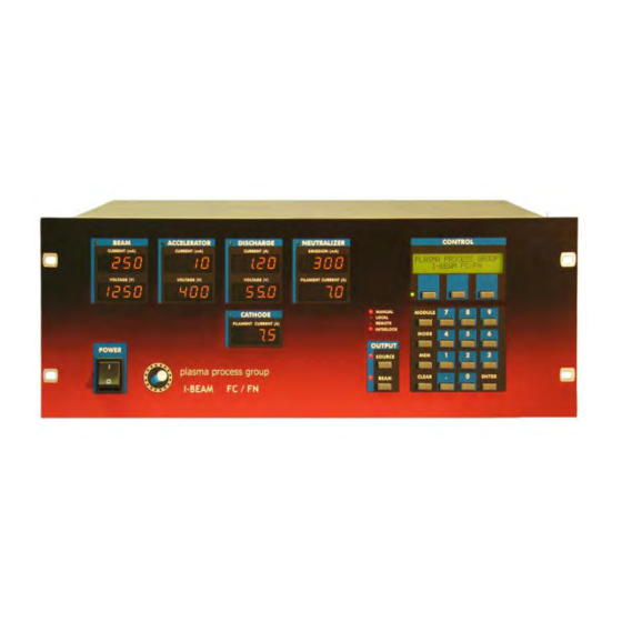
Section 4.1: Power supply layout The IBEAM FC / FN is a single chassis that contains the 5 individual power supplies described earlier in Figure 3. The user interface is the front panel and its layout is depicted in Figure 4.1. The output displays are used to provide voltage and current readings on the individual power supplies. -
Page 27: Keypad Entry And Power Supply Adjustments
Section 4.2: Keypad Entry and Power Supply Adjustments Adjustments or new target values to the individual power supplies can be input using the keypad. A CLEAR and ENTER key are provided. In order to select a specific power supply, repeatedly press the MODULE button. - Page 28 The options for each module in the main display will utilize abbreviations. The following is a listing of these abbreviations, the corresponding parameter and description. The specific module and acceptable range are also provided. Consult the source check-out sheet for typical values. MODULE ABBREVIATION PARAMETER AND DESCRIPTION ACCEPTABLE RANGE...
- Page 29 All values are entered as TARGETS. When the SOURCE and BEAM are ON, the modules will ramp to these target values. If a target value cannot be achieved, an alarm will trigger. See Chapter 6 for a listing of the power supply alarms.
-
Page 30: User Interface Examples
Section 4.3: User interface examples The following are examples of how to set target values and other user interface navigation. Example 1: Put the IBEAM in LOCAL mode and select the Cathode module. STEP 1) Press MODE button until LOCAL mode is selected. STEP 2) Press MODULE button until Cathode supply is selected. - Page 31 Example 9: Adjust the cathode filament current limit to 6.0 A. STEP 1) Press MODULE button until Control module indicator LED is ON. STEP 2) Select SETUP in the control keys. CATH I LIMIT should be displayed. STEP 3) Use keypad to type 6.0, and then ENTER. Example 10: Adjust the E/B ratio to 150%.
-
Page 32: Mode Indicator And Adjustments
Increasing the cathode filament current will increase the emission of electrons into the discharge chamber. As this is done, the plasma density increases in the discharge chamber, thereby more ions can be extracted and an increased beam current is observed. - Page 33 LOCAL mode is useful for applications requiring a constant beam current (or dose) on a target or substrate. The IBEAM controls the cathode filament current to maintain a steady beam current. In REMOTE mode, the IBEAM essentially behaves the same as LOCAL mode. REMOTE refers to the interface with the power supply utilizing the RS232 connection.
-
Page 34: Beam/Source On/Off
Section 4.5: Beam/Source ON/OFF The power supply has two output ON/OFF buttons labeled SOURCE and BEAM. When the SOURCE button is toggled to ON, power is applied to the cathode and neutralizer filaments. The discharge supply is also turned on. As the cathode filament is heated up to emit electrons, the discharge supply will ramp to about 150 V. -
Page 35: Operation Example
Section 4.6: Operation Example The following is a step by step example of operating the source. Step 1) Pumpdown The ion beam source requires a high vacuum environment for proper operation. As there are several different types of vacuum systems, general guidelines will be presented. Also, the vacuum environment will depend upon the application for the ion beam source. - Page 36 An established plasma discharge is indicated when the discharge current is detected. A reasonable discharge current range for source warm up is 0.5 to 0.7 A. If the discharge current is not within this range, increase or decrease the cathode heater current appropriately.
- Page 37 Presented in Table 4.4 are typical source warm up conditions. If the discharge current cannot be established, is excessively high, or other starting issues arise, please refer to Chapter 6 - Troubleshooting. Table 4.4: Typical warm up data Source Pressure Cathode Discharge Beam...
- Page 38 If the LOCAL mode is selected, a target value for beam current can be set in the BEAM module. When the BEAM button is pressed, the power supply will regulate the discharge current by adjusting the cathode heater to extract the target beam current. Step 5) Adjusting the beam conditions.
- Page 39 Table 4.7: Electron back-streaming occurs at an accelerator voltage of 50 V. Optimized is 100V. Source Pressure Cathode Discharge Beam Accelerator Neutralizer Heater Heater Emission (Torr) (V) (mA) (mA) (mA) 8 cm 5 sccm Ar 3.96 0.33 1250 5 sccm Ar 3.96 0.33 1250...
-
Page 40: Chapter 5: Remote Control
Chapter Remote Control The IBEAM can be controlled with a computer interface via RS232 communication link or using the remote switch feature. The RS232 link is provided at the USER COM port located on the rear of the unit (see Chapter 3). Below is the pin-out and wiring diagram for the connection. Section 5.1: RS232 Communications Figure 5.1: Pin-outs and electrical connections for... - Page 41 A quick reference list of standard commands and their description are: COMMAND DESCRIPTION A Attention, put IBEAM in REMOTE mode AB Set A/B ratio AC Auto cathode mode AV Set accelerator voltage B Turn beam on/off BE Set beam current tolerance BI Set beam current BV Set beam voltage CI Set the cathode filament current...
- Page 42 Commands are sent to the IBEAM with carriage return <cr>. The IBEAM will respond with an echo of the command followed by a specific response. If an invalid command is sent, the IBEAM will respond with a <lf><cr>?<lf><cr><eot>, where <lf> is a line feed and <eot> is end of transmission. Certain commands are sent with additional values included before the carriage return <cr>.
-
Page 43: Command Details
Section 5.2: Command Details Serial command: Description: Attention and put IBEAM in REMOTE mode. Usage: A<cr> Example: Send “A<cr>”. The IBEAM will switch to REMOTE mode (if not already in REMOTE mode). Response: <lf><cr>OK<lf><cr><eot> Serial command: Description: Set the accelerator to beam (A/B) ratio. Usage: AB(0-99)<cr>... - Page 44 Serial command: Description: Turn the beam on or off Usage: B(1 or 0)<cr> Example: Send “B1<cr>”. The beam will turn on. Send “B0<cr>”. The beam will turn off. Response: <lf><cr>OK<lf><cr><eot> Serial command: Description: Set the beam current tolerance limit. Usage: BE(0-99)<cr>...
- Page 45 Serial command: Description: Set the cathode filament current. Usage: CI(0.0-20.0)<cr> Example: Send “CI4.2<cr>”. The cathode filament current will bet set to 4.2 A. After the source is turned on the power supply will ramp the cathode filament current to 4.2 A. Acceptable range is from 0.0 to 20.0 A. The source check-out sheet should be consulted for normal ranges.
- Page 46 Serial command: Description: Set the maximum discharge current threshold for use with Auto Cathode mode. Usage: DT(0.0-6.0)<cr> Example: Send “DT1.25<cr>”. The discharge current threshold will be set to 1.25 A. If the discharge current exceeds 1.25A, then the power supply will stop automatically ramping up the Cathode current (in Auto Cathode mode only).
- Page 47 Serial command: Description: Enable or disable the E-24 error for E/B ratio. Usage: NE(0 or 1)<cr>. 0 enables, and is the default. 1 disables. Example: Send “NE1<cr>”. The E-24 error alarm will be disabled. When the emission to beam ratio is not met, the E-24 error will not flash or function. Response: <lf><cr>OK<lf><cr><eot>...
- Page 48 Serial command: Description: Recall conditions from memory. Usage: R(0-9)<cr> Example: Send “R2<cr>”. The beam conditions stored in memory location 2 will be recalled. Acceptable range is from 0 to 9. Each memory location stores beam current, beam voltage, accelerator voltage, discharge voltage, cathode filament current and neutralizer filament current.
- Page 49 Serial command: Description: Recall conditions from memory in compressed format. Parameter Units AAAAA= Beam Voltage Volts BBBBB= Beam Current CCCCC= Accelerator Voltage Volts DDDDD= A/B Ratio EEEEE= Cathode filament limit Amps FFFFF= PBN body voltage limit Volts GGGGG= Discharge Voltage Volts HHHHH= Beam Current Tolerance IIIII= Discharge Current Threshold...
- Page 50 Serial command: Description: Display Power Supply Type Letter Description Designator Type Power Supply IBEAM 601 Cathode Type Beam Type Normal Neutralizer Type Filament Discharge Type Accelerator Type Normal Usage: V<cr> Example: Send “V<cr>”. Response: <lf><cr>IBEAM 601 FCFN<lf><cr><eot> Serial command: Description: Display Power Supply and version Usage: V1<cr>...
-
Page 51: Operation Example
Section 5.3: Operation example The following is a line-by-line short example of how turn on the beam and monitor its conditions. Each line represents a command sent to the IBEAM. The time duration between each command line should be a least one (1) second. For data logging operations, it is recommended requesting the running conditions should not be performed more than once (1 time) per second. -
Page 52: Remote Switches
Section 5.4: Remote switches For faster control, certain functions of the IBEAM can be performed using remote switches. The remote switch link is provided at the INTERLOCK port located on the rear of the unit (see Chapter 3). Specifically, the source and beam switch can be toggled remotely. For these features to work, the remote switch must be enabled from the CONTROL module (see Chapter 4). -
Page 53: Chapter 6: Troubleshooting
Most issues arise from electrical shorting or openings that disrupt proper operation. These issues may not present themselves easily, say with a multi-meter, as it may be a plasma short or a thermal open that creates the issue. CAUTION Components that are usually safe may be shorted to power. -
Page 54: Power Supply Error Codes
Output of module 1. Electrical short – Check electrical connections. is to high 2. Plasma short – Check the source and feedthru for electrical wire proximity problems or coated insulators. 3. Gas flow is too high – Check gas flow level. -
Page 55: Starting The Source
Section 6.2: Starting the Source Table 6.2: Problems with CATHODE, ANODE and DISCHARGE PROBLEM POSSIBLE PROBLEMS AND SOLUTIONS DESCRIPTION Cathode filament 1. Filament failure – Check and replace filament current is zero 2. Faulty connection – Check cable and feedthru connections (Table 6.5). 3. -
Page 56: Turning On The Beam
1. Screen grid is electrically shorted – Check body electrical connections. than normal Look for signs of plasma shorts, coated insulators and electrical lead wire proximity issues. 2. If both accel and beam current are high - Check the grid alignment and spacing. -
Page 57: Neutralizer Operation
Section 6.4: Neutralizer Operation Table 6.5: Problems with the neutralizer PROBLEM POSSIBLE PROBLEMS AND SOLUTIONS DESCRIPTION Neutralizer filament 1. Filament failure – Check and replace filament current is zero 2. Faulty connection – Check cable and feedthru connections (Table 6.5). 3. -
Page 58: Special Testing
Section 6.5: Special Testing CAUTION These tests require that the power supply is powered off. Turn the front panel EPO to OFF. Turn the rear panel main switch to OFF. Table 6.5: Diagnostics and testing procedures PROBLEM POSSIBLE PROBLEMS AND SOLUTIONS DESCRIPTION Cathode filament 1. - Page 59 If the accelerator grid voltage is set too low, it is possible for electrons from the neutralizer to migrate into the discharge plasma. This condition is referred to as electron backstreaming. Electron backstreaming will lead to erroneous beam current readings and will result in a lower etch rate on the target (or a lower deposition rate).
-
Page 60: Chapter 7: Specifications
Chapter Specifications Below are specifications for the IBEAM FC/FN power supply. Specifications Power Outputs Five individual supplies to drive a filament cathode and neutralizer source beam supply 1500 VDC,500 mA accelerator supply 1000 VDC, 50 mA discharge supply 80 VDC, 6 A...
Need help?
Do you have a question about the IBEAM FC and is the answer not in the manual?
Questions and answers