Advertisement
Quick Links
European standard EN 1004
www.marchetti.eu
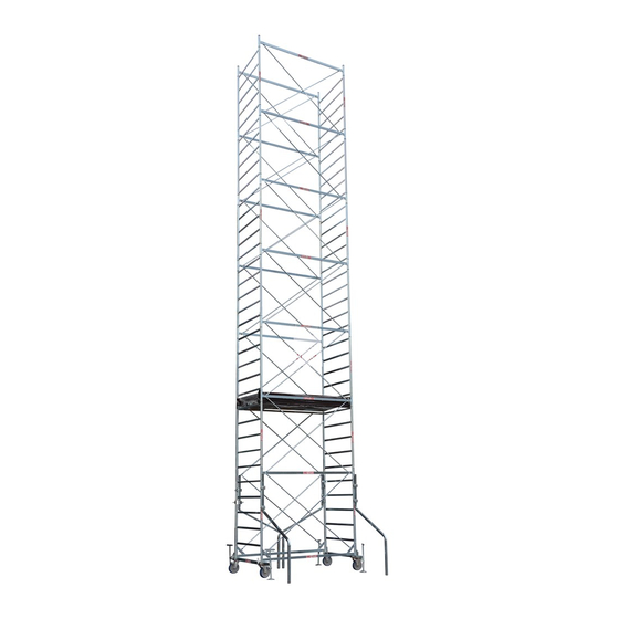
MOBILE ACCESS TOWER
SYSTEM
System 120x200
System 120x180
System 100x200
System 100x180
System 75x200
System 75x180
The products identified in this handbook have been ma-
nufactured by MARCHETTI s.r.l. With QUALITY SYSTEM
MANAGEMENT, certified by Tuv Italia, in accordance with
ISO 9001
Instructions Manual EN 1298 – IM – it x en
Mobile access towers must only be used for finishing, maintenance and similar works. This instructions
manual contains important instructions on use, maintenance and safety of the mobile access tower;
the operator must be completely aware of them before use. Strictly complying with this manual
means working in compliance with the provisions of the current standard on health and safety in the
workplace Leg. Decree. 09.04.2008 no. 81.
MARCHETTI S.r.l.
Via Piemonte, 22
06062 Città della Pieve - Perugia - Italy
Instructions for use
and maintenance
CUSTOMER ASSISTANCE DOCUMENT
1
ENG
NR. 35 REV. 8 OF 27/08/2020
Code 10731
info@marchetti.eu
www.marchetti.eu
Advertisement

Related Manuals for Marchetti System 120x200

Summary of Contents for Marchetti System 120x200
- Page 1 System 100x180 System 75x200 System 75x180 The products identified in this handbook have been ma- nufactured by MARCHETTI s.r.l. With QUALITY SYSTEM MANAGEMENT, certified by Tuv Italia, in accordance with ISO 9001 CUSTOMER ASSISTANCE DOCUMENT NR. 35 REV. 8 OF 27/08/2020 Code 10731 Instructions Manual EN 1298 –...
-
Page 2: Warranty
WARRANTY All MARCHETTI products are covered by the company’s official guarantee, pursuant to applicable norms. The guarantee is immediately effective and is ratified by the invoice accompanying the goods. A product found to be faulty is guaranteed. We shall accept no responsibility for products used incorrectly or damaged during use or transport. -
Page 3: Reference Standards
“Consumers’ Code”. DESIGNATION, CLASS, CAPACITY System 120x200 working tower EN 1004 – 3 – 8 / 12 XXCD. System 120x180 working tower EN 1004 – 3 – 8 / 12 XXCD. System 100x200 working tower EN 1004 – 3 – 8 / 8,5 XXCD. - Page 4 Base Overall load max n° of H max mobile H max mobile working tower EN1004 (m) tower D.LGS.81 dimensions permitted ( kg) platform 120x200 12,50 17,00 120x180 12,50 14,00 100x200 9,50 11,00 100x180 9,50 9,50 75x200 8,00 8,00 75x180...
-
Page 5: Declaration Of Conformity
Città della Pieve (Pg) - Via Piemonte, 22: DECLARES - that the mobile tower called SYSTEM 120X200 - 120X180 - 100X200 - 100X180 - 75X200 - 75X180 are manufactured in compliance with Leg. Decree 09.04.2008 no. 81 and in particular the Technical... - Page 6 IDENTIFICATION SYSTEM 120X200 Table of elements composing the configurations Weight CONFIGURATIONS Cod. Component Elements A4 A5 20579 EXTRACTABLE BASE 20551 Wheel-bearing section for extr. Base S120 12,70 20550 Wheel-bearing section for extr. Base S120 12,60 20552 Base brace - 200...
- Page 7 IDENTIFICATION SYSTEM 120X180 Table of elements composing the configurations Weight CONFIGURATIONS Cod. Component Elements A4 A5 20580 EXTRACTABLE BASE 20551 Wheel-bearing section for extr. Base S120 12,70 20550 Wheel-bearing section for extr. Base S120 12,60 20554 Base brace - 180 6,00 20318 Extractable adjustable foot 3,50...
- Page 8 COMPONENTS ELEMENTS Extractable base Tower H=1,50 m Terminal tower H=0,90 m Work platform SYSTEM 120X200 Guardrail bars SYSTEM 120X180 Guardrail...
- Page 9 SYSTEM EN 1004 CONFIGURATION SYSTEM 120X200 SYSTEM 120X180 CONFIGURATION INSIDE AND OUTSIDE OF BUILDING CONFIGURATION INSIDE OF BUILDING WITHOUT TERMINAL TOWER H=0,90 m CONFIGURATIONS H max mobile tower 2,00 3,50 5,00 6,50 8,00 9,50 11,00 12,50 H max work platform...
- Page 10 IDENTIFICATION SYSTEM 100x200 Table of elements composing the configurations Weight CONFIGURATIONS Cod. Component Elements 20575 EXTRACTABLE BASE 20547 Wheel-bearing section for extr. Base S100 12,30 20546 Wheel-bearing section for extr. Base S100 12,20 20552 Base brace - 200 6,40...
- Page 11 IDENTIFICATION SYSTEM 100x180 Table of elements composing the configurations Weight CONFIGURATIONS Cod. Component Elements 20576 EXTRACTABLE BASE 20547 Wheel-bearing section for extr. Base S100 12,30 20546 Wheel-bearing section for extr. Base S100 12,20 20554 Base brace - 180 6,00 20318 Extractable adjustable foot 3,50 30523 Handgrip screw M14x50 0,14...
- Page 12 COMPONENTS ELEMENTS Extractable base Tower H=1,50 m Terminal tower H=0,90 m Work platform SYSTEM 100X200 Guardrail bars SYSTEM 100X180 Guardrail...
- Page 13 SYSTEM EN 1004 CONFIGURATION SYSTEM 100X200 SYSTEM 100X180 CONFIGURATION INSIDE AND OUTSIDE OF BUILDING CONFIGURATION INSIDE OF BUILDING WITHOUT TERMINAL TOWER H=0,90 m CONFIGURATIONS H max mobile tower 2,00 3,50 5,00 6,50 8,00 9,50 H max work platform 1,00 2,50 4,00 5,50 7,00...
- Page 14 IDENTIFICATION SYSTEM 75x200 Table of elements composing the configurations Weight CONFIGURATIONS Cod. Component Elements 20577 EXTRACTABLE BASE 20548 Wheel-bearing section for extr. Base S 75 11,00 20549 Wheel-bearing section for extr. Base S 75 10,90 20552 Base brace - 200...
- Page 15 IDENTIFICATION SYSTEM 75x180 Table of elements composing the configurations Weight CONFIGURATIONS Cod. Component Elements 20578 EXTRACTABLE BASE 20548 Wheel-bearing section for extr. Base. S 75 11,00 20549 Wheel-bearing section for extr. Base S 75 10,90 20554 Base brace - 180 6,00 20318 Extractable adjustable foot...
- Page 16 COMPONENTS ELEMENTS Extractable base Tower H=1,50 m Terminal tower H=0,90 m Work platform SYSTEM 75X200 Guardrail bars SYSTEM 75X180 Guardrail...
- Page 17 SYSTEM EN 1004 CONFIGURATION SYSTEM 75X200 SYSTEM 75X180 CONFIGURATION INSIDE AND OUTSIDE OF BUILDING WITHOUT TERMINAL TOWER H=0,90 m CONFIGURATIONS H max mobile tower 2,00 3,50 5,00 6,50 8,00 H max work platform 1,00 2,50 4,00 5,50 7,00 H tower ( H= 1,50 m) n°...
-
Page 18: Assembly And Dismantling
COMPLETE GUARDRAIL EN 1004 The lateral protection consists of two steel pipes frames joined by two steel cross elements that en- sure protection at both intermediate and top positions. They are hooked to the lateral cross-pieces to avoid accidental detachment. Use as working top guardrail. - Page 19 ASSEMBLY INSTRUCTIONS SYSTEM TOWERS OVER EXTRACTABLE BASE Having checked that all of the requirements, proceed with the assembly of the base section: •Join the two wheel-bearing sections with the two base connecting braces using the four handgrip screws supplied; • Before tightening the screws fully, position the first two lateral frames; taking care to position the pawls towards the inside and the labels towards the outside.
- Page 20 Always try to increase the dimensions of the floor contact surface area. Close the two front clampson on the stabilizer, making sure it rests firmly on the ground, and then tighten the corresponding eyebolt nuts. Repeat the same sequence of operations for the other three tower uprights;...
- Page 21 • At the summit of the mobile access tower additional overlying structures should not be mounted, and shielding of any kind, such as lattice, tarpaulin, etc., should not be fitted. PRELIMINARY CHECKS • Verify that the mobile access tower has been assembled in an upright position. Refer to the supplier’s instructions regularly and follow them scrupulously to guarantee a perfect execution;...
- Page 22 • It is mandatory to keep a distance of at least 5.00 metres from power line; • Once moved, engage the brakes on the four wheels, level the tower again and move the stabilizers until perfectly in contact with the ground.
- Page 23 • The stabilizers (cod: 20525, 20753, 21557) are component of the base, essential to mobile access towers higher than 7.00 m and they always must be present on such towers, both during use and in every movement. Put them vertically at about 10 mm to the ground. ACCESSING THE WORK PLATFORM It is obligatory to gain access to the work platforms from inside the tower;...
- Page 24 KIT LANDING ON ROOFS AND COVERINGS Mobile towers can also be used for landing on roofs and roofs, in the configurations indicated below, with the appropriate landing kit. The landing kit consists of two brackets for the safe locking of the short toe boards and 2 steel rods with anti-slip device at the ends.
- Page 26 SIX-MONTHLY SERVICE Mobile access tower Mod. Service of Numerical verification of components Cleaning of components Integrity of components Absence of oxidised areas Integrity of welding Lubrication of tightening screws Lubrication of pins and sleeves Efficiency of wheels and braking devices...
- Page 27 SIX-MONTHLY SERVICE Mobile access tower Mod. Service of Numerical verification of components Cleaning of components Integrity of components Absence of oxidised areas Integrity of welding Lubrication of tightening screws Lubrication of pins and sleeves Efficiency of wheels and braking devices Integrity of work platforms Integrity of railings Integrity of toe boards...
- Page 28 SIX-MONTHLY SERVICE Mobile access tower Mod. Service of Numerical verification of components Cleaning of components Integrity of components Absence of oxidised areas Integrity of welding Lubrication of tightening screws Lubrication of pins and sleeves Efficiency of wheels and braking devices...
- Page 29 SIX-MONTHLY SERVICE Mobile access tower Mod. Service of Numerical verification of components Cleaning of components Integrity of components Absence of oxidised areas Integrity of welding Lubrication of tightening screws Lubrication of pins and sleeves Efficiency of wheels and braking devices Integrity of work platforms Integrity of railings Integrity of toe boards...
- Page 30 SIX-MONTHLY SERVICE Mobile access tower Mod. Service of Numerical verification of components Cleaning of components Integrity of components Absence of oxidised areas Integrity of welding Lubrication of tightening screws Lubrication of pins and sleeves Efficiency of wheels and braking devices...
- Page 31 SIX-MONTHLY SERVICE Mobile access tower Mod. Service of Numerical verification of components Cleaning of components Integrity of components Absence of oxidised areas Integrity of welding Lubrication of tightening screws Lubrication of pins and sleeves Efficiency of wheels and braking devices Integrity of work platforms Integrity of railings Integrity of toe boards...
- Page 32 MARCHETTI S.r.l. info@marchetti.eu Via Piemonte, 22 www.marchetti.eu 06062 Città della Pieve - Perugia - Italy...
Need help?
Do you have a question about the System 120x200 and is the answer not in the manual?
Questions and answers