Table of Contents

Related Manuals for DataApex Clarity INT7

Summary of Contents for DataApex Clarity INT7
- Page 1 INT7 A/D CONVERTER Clarity Hardware Code/Rev.: M058/80B Date: 8/24/2020 Phone: +420 251 013 400 DataApex Ltd. Fax: +420 251 013 401 Petrzilkova 2583/13 clarity@dataapex.com 158 00 Prague 5 www.dataapex.com The Czech Republic...
- Page 2 Clarity ® , DataApex ® and ® are trademarks of DataApex Ltd. Microsoft ® and Windows TM are trademarks of Microsoft Corporation. DataApex reserves the right to make changes to manuals without prior notice. Updated manuals can be downloaded from www.dataapex.com. Author: zte...
-
Page 3: Table Of Contents
3.4 Clarity Configuration 3.4.1 Measuring on Multiple Instruments 3.4.2 Using multiple INT7 converters 4 Using the INT7 Card 4.1 DataApex INT7 Setup 4.2 Method Setup 4.2.1 Method Setup - Acquisition 4.2.2 Method Setup - Measurement 4.3 Digital Inputs and Outputs 4.4 Device Monitor... - Page 4 INT7 A/D Converter Table of Contents To facilitate the orientation in the INT7 A/D Converter manual and Clarity chromatography station, different fonts are used throughout the manual. Meanings of these fonts are: Instrument (blue text) marks the name of the window to which the text refers. Open File (italics) describes the commands and names of fields in Clarity, parameters that can be entered into them or a window or dialog name (when you already are in the topic describing the window).
-
Page 5: Int7 Acquisition Card
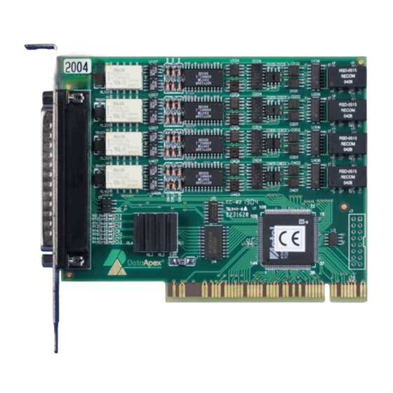
INT7 A/D Converter 1 INT7 Acquisition card 1 INT7 Acquisition card This manual describes the use of the INT7 A/D Converter with the Clarity software ver. 2.7 and later. INT7 is an internal 24-bit A/D converter card that measures the voltages of chromatographic and electrochemical detectors. - Page 6 INT7 A/D Converter 1 INT7 Acquisition card Advantages of the INT A/D converter No loss of input signal during integration. There are no time delays during which the converter fails to integrate the input signal. No continuous servicing of the input analog switches, which would otherwise cause errors (offset, noise).
-
Page 7: Requirements
INT7 A/D Converter 2 Requirements 2 Requirements The INT7 internal PCI A/D converter can be used with the Clarity software on PC’s using the OS described in the Tab 1 on pg 3. The PC must have a free PCI slot for your INT7 card. Note: Full size PCI 2.0, 32 bit PCI slot for 5V 32 bits half-length extension card is required. -
Page 8: Installation
INT7 A/D Converter 3 Installation 3 Installation Ensure that you have Administrator access rights in your Windows OS before you proceed with the installation. 3.1 The INT7 Install the Clarity software from the DVD-ROM. Caution: Install Clarity before inputting any devices. In Windows 2000, XP and later the drivers were copied to your computer during the installation of the Clarity software. - Page 9 INT7 A/D Converter 3 Installation a set of one signal wire, one starting wire and one digital output wire. The 2-channel INT7 card would thus have the cable with following parts: Signal cables Labeled DET1 and DET2 , the cables are supplied as standard without connectors [bare stripped and tinned endings –...
-
Page 10: Connection With Chromatograph
– it is necessary to read through the instructions for the corresponding chromatograph. All current DataApex A/D Converters INT7, INT9, U-PAD, U-PAD2 and Net-PAD use the same standard INT7 Connector. Note: A description of the INT7 connector can be found in the chapter "Tables and specifications"... -
Page 11: Connection Of Starting Cables
INT7 A/D Converter 3 Installation Note: This SV9 Terminal Board is not suitable for applications with small signals or with high electromagnetic interference. This is because the SV9 Terminal Board uses leads and screw contacts that are not shielded. 3.3.2 Connection of starting cables Starting input reacts to a change of the TTL level (5 V / 0 V) or to a connection by any contact (button, contact of relay). -
Page 12: Clarity Configuration
INT7 A/D Converter 3 Installation 3.4 Clarity Configuration Fig 4: System Configuration Start the Clarity station by clicking the icon on the desktop. Invoke the System Configuration dialog accessible from the Clarity window using the System – Configuration... command. ① Press the Add button (See Fig 4 on pg 8 .) to invoke the Available... - Page 13 Enter the detector names in Name fields for individual channels, set signal units. Note: A detailed description of this dialog can be found in the chapter "DataApex INT7 Setup" on pg 12. Press the OK button. ④ The INT7 will appear in the Setup Control Modules list...
-
Page 14: Measuring On Multiple Instruments
INT7 A/D Converter 3 Installation 3.4.1 Measuring on Multiple Instruments When measuring on multiple instruments using only a single INT7 to gather data, rather than dragging the entire INT7 icon from the Setup ① Control Modules list , drag the individual detector signals (FID, UV-VIS ②... - Page 15 INT7 A/D Converter 3 Installation Fig 7: System Configuration – multiple INT7s Individual detectors from all cards can be assigned to multiple instruments and combined together arbitrarily. In this example, all signals from INT7 A/D Card 1, as well as all signals from INT7 A/D Card 2 and one signal ( Pressure ) from U- PAD2 are assigned to the Instrument 1 , while the second signal (UV) from U-PAD2 is assigned to the Instrument 2.
-
Page 16: Using The Int7 Card
INT7 converter and since it depends on the type of connected detector, it is not going to be changed often. Fig 9: DataApex INT7 Setup Number of Channels Indicates the number of data acquisition channels. - Page 17 INT7 A/D Converter 4 Using the INT7 Card Channel 1 (to 4) For each channel of the INT7 A/D Card the name of the signal can be edited in the Name field and the Set Units... button can be used to change other signal parameters.
- Page 18 INT7 A/D Converter 4 Using the INT7 Card necessary time lags at the start of the acquisition are significant. When measuring multi-detector chromatograms it will minimize the time shift between detector signals and thus improve the detection of peaks. Note: Synchronize Start with Digital Input reflects the settings of the Contact Closure/Opening of the External Start/Stop option in the Method Setup -...
-
Page 19: Method Setup
INT7 A/D Converter 4 Using the INT7 Card 4.2 Method Setup Parameters of the Method Setup - Acquisition Method Setup - Measurement dialogs depend on the type of analysis (measuring conditions), so they can be specific for various types of analyses. This is the reason for them to be a part of the method. - Page 20 INT7 A/D Converter 4 Using the INT7 Card Higher sampling rate allows for the measurement of narrower peaks, but it also means a larger amount of data which affects the size of the resulting chromatogram and the speed of its processing. Sample rate sufficient for successful peak detection is about 20 samples per narrowest peak.
-
Page 21: Method Setup - Measurement
INT7 A/D Converter 4 Using the INT7 Card 4.2.2 Method Setup - Measurement Fig 14: Method Setup - Measurement External Start/Stop Enables control from an external signal. Note: The input used for an external start from a chromatograph can be set in System Configuration dialog, see Fig 4 on pg 8. -
Page 22: Digital Inputs And Outputs
INT7 A/D Converter 4 Using the INT7 Card 4.3 Digital Inputs and Outputs The INT7 A/D Converter contains eight digital TTL outputs , where the first four are also designed as relay contacts. The converter contains four digital inputs IN1 - IN4. The first two inputs are also equipped with optocouplers. -
Page 23: Device Monitor
(HIGH), light switched off (gray icon) to logical zero (LOW). Descriptions Shows the description indicating the meaning of individual input. The names of all digital inputs can be set in the DataApex INT7 Setup dialog. Output no. Lists the serial numbers of individual outputs. -
Page 24: Troubleshooting
INT7 A/D Converter 5 Troubleshooting 5 Troubleshooting If you will not find your answers here, use the www.dataapex.com website where the Support menu will navigate you to frequently asked questions (FAQ), Clarity email conference archive or contact to DataApex helpdesk. -
Page 25: Problems With Int7
INT7 cannot be added to Setup Control Modules in the System Configuration dialog, showing the "Cannot create detector" error message. Double-clicking on the device will not invoke the DataApex INT7 Setup dialog. The Data Acquisition icon in the Instrument window is not active (this problem may also have another cause. -
Page 26: How To Check The Int7 Driver
Fig 17: Device Manager in Windows XP Error status of the driver may be one of the following: ▌ If the “Chromatography Devices – DataApex Acquisition Device Model 7.xx” - item does not appear, then the driver has not been installed. - Page 27 INT7 A/D Converter 5 Troubleshooting Solution: Double-click the item to invoke the General tab and activate the driver by clicking on the Enable this device button. ▌ The item does appear and there are no error symbols around it. A driver for a different type of Windows operating system was possibly installed thereby replacing the correct driver.
-
Page 28: Manual Installation
INT7 A/D Converter 5 Troubleshooting 5.3 Manual Installation 5.3.1 Installation and reinstallation in Windows XP and later During start-up, Windows should automatically recognize the new Plug and Play device and start the Add Hardware Wizard. Note: If the wizard does not occur, use the Start - Control Panel – Add Hardware to invoke installation. - Page 29 INT7 A/D Converter 5 Troubleshooting Fig 20: Step 3 of Hardware Installation Wizard Select the Install from a list or specific location (Advanced) option and click Next. Fig 21: Step 4 of Hardware Installation Wizard Select Don't search. I will choose the driver to install. and click the Next button.
- Page 30 INT7 A/D Converter 5 Troubleshooting Fig 23: Step 6 of Hardware Installation Wizard Click the Browse... button and in the displayed Locate File dialog browse to the main folder of the Clarity Station and HW_DRIVERS\INT7 subfolder (C:\CLARITY\HW_DRIVERS\INT7 by default). Select the CSWINT7.INF file and click the Open button.
-
Page 31: Reinstallation Of Drivers Using The System Restore Point
INT7 A/D Converter 5 Troubleshooting 5.3.2 Reinstallation of drivers using the System Restore Point Use the System Restore Point in MS Windows XP and later to uninstall the incorrect drivers. Go to Start – Programs – Accessories – System Tools – System Restore in Windows XP or press the Windows key on your keyboard and type "System Restore"... -
Page 32: Reinstallation Of Drivers In Windows 2000
Fig 25: Device Manager in Windows 2000 If the " DataApex Acquisition device, model 7.XX " item is missing, Windows has automatically installed incorrect driver. If you are able to locate which device was mistakenly installed instead of the INT7 driver, you can open its Properties and Update this driver. -
Page 33: Installing The Correct Driver Manually
INT7 A/D Converter 5 Troubleshooting ② Sort the files according to Modified column and locate the last modified *.PNF file ③. ③ Also locate the corresponding *.INF file and delete both of them. Fig 26: Windows Explorer Continue to install the correct driver manually (described in the chapter "Installing the correct driver manually"... - Page 34 INT7 A/D Converter 5 Troubleshooting Fig 28: Step 2 of Add/Remove Hardware Wizard In the Devices list select the Add a new device and click the Next button. Fig 29: Step 3 of Add/Remove Hardware Wizard Select No, I want to select the hardware from a list and click the Next button.
- Page 35 Clarity is installed ( C:\CLARITY\BIN by default), in the HW_DRIVERS\INT7 subfolder. Then click the OK button. Fig 32: Step 6 of Add/Remove Hardware Wizard In the Models list select the "DataApex Acquisition device, Model 7.XX" and click the Next button. In the remaining dialogs press the Next button.
-
Page 36: Data Acquisition - Non-Functional
INT7 A/D Converter 5 Troubleshooting 5.4 Data Acquisition - non-functional ▌ Gray icon with the heading DISABLED and non- functional Monitor - Data Acquisition command. Fig 33: Data Acquisition disabled Other manifestations of this error are also: Method Setup - Acquisition tab missing, Method - Acquisition command non-functional, Run, Stop, Abort and other similar commands non- functional in the... - Page 37 INT7 A/D Converter 5 Troubleshooting If your A/D card is not in the left-hand list Setup Control Modules, add it using the Add button and repeat the previous step. Note: More information on the System Configuration dialog can be found in the chapter "Clarity Configuration"...
-
Page 38: Data Acquisition - Simulated
Configuration... command and check the tab of the corresponding Instrument - Instrument X . If it only has the detector signals from the DataApex DEMO detector, it is necessary to reconfigure it. You can find more information how to add a detector in the chapter "Clarity Configuration"... -
Page 39: Tables And Specifications
INT7 A/D Converter 6 Tables and specifications 6 Tables and specifications 6.1 Description of the INT7 connector (Male) Fig 38: Connector pins Tab 3: Description of the connector pins: Description + Input of the 1st channel - Input of the 1st channel AGND Ground of the analog channels Digital input (of the 1st channel). -
Page 40: Parameters Of Digital Inputs And Outputs
INT7 A/D Converter 6 Tables and specifications Fig 39: Standard INT7-compatible cable for two detectors 6.2 Parameters of Digital Inputs and Outputs Digital Outputs The card contains eight digital TTL outputs (OUT1-OUT8) with a maximum permissible current of 20 mA at both levels. The first four outputs are also equipped with relay contacts (OUT1S1/OUT1S2- OUT4S1/OUT4S2). -
Page 41: Int7 - Ce Conformity Declaration
INT7 A/D Converter 6 Tables and specifications 6.3 INT7 - CE Conformity Declaration Fig 40: CE Conformity declaration - INT7 - 37 -... -
Page 42: Technical Data
INT7 A/D Converter 6 Tables and specifications 6.4 Technical data Tab 4: Technical data of the INT7 board: Parameter Description Converter type: 24-bit δΣ (delta – sigma) Analog inputs: differential Number of 1, 2 or 4 fully independent and isolated channels: unipolar and bipolar, each channel independently 156, 1 250 Input range:...
Need help?
Do you have a question about the Clarity INT7 and is the answer not in the manual?
Questions and answers