Table of Contents

Related Manuals for DataApex Colibrick

Summary of Contents for DataApex Colibrick
- Page 1 Clarity Hardware Colibrick A/D Converter Code/Rev.: M149/50C Date: 4.12.2013 Phone: +420 251 013 400 DataApex Ltd. Fax: +420 251 013 401 Petrzilkova 2583/13 clarity@dataapex.com 158 00 Prague 5 www.dataapex.com The Czech Republic...
- Page 2 Clarity ® , DataApex ® and ® are trademarks of DataApex Ltd. Microsoft ® and Windows TM are trademarks of Microsoft Corporation. DataApex reserves the right to make changes to manuals without prior notice. Updated manuals can be downloaded from www.dataapex.com. Author: zte...
-
Page 3: Table Of Contents
5 Troubleshooting 5.1 Locate your problem 5.2 Problems with Colibrick 5.2.1 How to check the proper installation of the Colibrick driver 5.2.2 Manual installation 5.2.2.1 Installation and reinstallation in Windows 8, 7 and Vista 5.2.2.2 Installation and reinstallation in Windows XP 5.2.2.3 Reinstallation of drivers using the System Restore Point... - Page 4 Table of Contents Clarity Hardware To facilitate the orientation in the Colibrick A/D Converter manual and Clarity chromatography station, different fonts are used throughout the manual. Meanings of these fonts are: Instrument (blue text) marks the name of the window, to which the text refers.
-
Page 5: Colibrick Acquisition Device
Colibrick A/D Converter 1 Colibrick acquisition device 1 Colibrick acquisition device This manual describes the use of the Colibrick A/D Converter with the Clarity software ver. 4.0 and newer. Colibrick is an external 24-bit A/D converter that measures the voltages of chromatographic and electrochemical detectors. -
Page 6: Front Panel Of The Colibrick Device
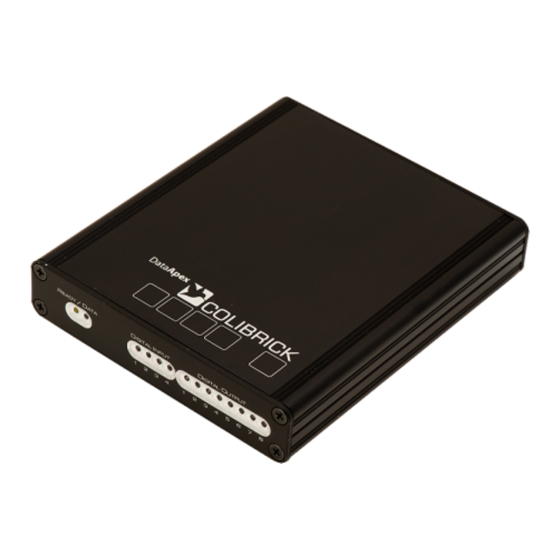
1 Colibrick acquisition device Clarity Hardware 1.1 Front panel of the Colibrick device The front panel contains LED indicators indicating the status of the device. Fig 2: Front panel of the Colibrick Ready (orange) LED status Indicates correct installation. Data (blue) LED status Indicates connection to the chromatography data station. - Page 7 Colibrick A/D Converter 1 Colibrick acquisition device Advantages of the Colibrick A/D converter No loss of input signal during integration. There are no time delays during which the converter fails to integrate the input signal. No continuous servicing of the input analog switches, which would otherwise cause errors (offset, noise).
-
Page 8: Requirements
Colibrick A/D Converter 2 Requirements 2 Requirements The Colibrick external USB A/D Converter can be used with the Clarity software on PC’s using the OS described in the Tab 1 on pg 4. The PC must have free USB slot. -
Page 9: Installation
The drivers were copied to your computer and installed automatically during the installation of the Clarity software. Note: The Colibrick device is detected by its S/N. If you later replace one by another, it is also necessary to reconfigure it in the Clarity System Configuration dialog. -
Page 10: Standard Cable For Clarity Station
3 Installation Clarity Hardware 3.2 Standard cable for Clarity station Fig 4: Cables for the Clarity station package The standard Clarity station package includes a cable composed of signal and starting cables for connecting the Clarity station to the chromatograph. Signal cables Labeled DET1 …... -
Page 11: Connection With Chromatograph
– it is necessary to read through the instructions for the corresponding chromatograph. All current DataApex A/D Converters Colibrick, INT7, INT9, U-PAD, U- PAD2 and Net-PAD use the same standard INT7 Connector. Note: A description of the INT7 connector can be found in the chapter "Tables... -
Page 12: Connection Of Starting Cables
3 Installation Clarity Hardware of the wiring, we supply a SV9 Terminal board with screw contacts for INT7, INT9, U-PAD, U-PAD2, Colibrick and Net PAD A/D converters. Note: This SV9 Terminal Board is not suitable for applications with small signals or with high electromagnetic interference. This is because the SV9 Terminal Board uses leads and screw contacts that are not shielded. -
Page 13: Clarity Configuration
(See Fig 6 on pg 9 .) to invoke the Available Control Modules dialog. You can specify the searching filter to simplify the finding of the driver. Select the Colibrick and press the Add button. DataApex Colibrick Setup dialog will appear. - 9 -... - Page 14 The Colibrick will appear in the Setup Control Modules list of the System Configuration dialog. Drag and drop the Colibrick icon from the Setup Control Modules list the left side of the System Configuration dialog to the chosen Instrument tab on the right side...
-
Page 15: Measuring On Multiple Instruments
3.4.1 Measuring on multiple instruments When measuring on multiple instruments using only a single Colibrick to gather data, rather than dragging the entire Colibrick icon from the Setup Control Modules list , drag the individual detector signals (FID, UV-VIS in this case) to separate Instruments . -
Page 16: Using Multiple Colibrick Converters
Individual converters can be assigned to multiple Instruments and combined together arbitrarily. In the example described in Fig 9 on pg 12., all signals from Colibrick 1 , as well as all signals from Colibrick 2 are assigned to the Instrument 1. -
Page 17: Using The Colibrick
Fig 10: DataApex Colibrick Setup Device Shows the serial number of selected Colibrick. If more than one Colibrick converter is attached to the PC, this field defines which Colibrick will be - 13 -... - Page 18 4 Using the Colibrick Clarity Hardware added and configured first or, in case of removing one Colibrick from the configuration, for specifying which one is still connected. Channel 1 (to 4) For each channel of the Colibrick A/D Converter the name of the signal can be edited in the Name field and the Set Units...
- Page 19 Measurement dialog. Caution: Turn this function ON only in case one of the digital inputs of the configured Colibrick is also set in the Ext. Start Dig. Input option in the System Configuration dialog. Device Setup This section allows to modify the naming of digital inputs and outputs and change the Mains Supply Frequency Suppression settings.
- Page 20 4 Using the Colibrick Clarity Hardware Note: In most parts of the Americas, the 60 Hz Mains frequency is usual, while the rest of the world tends to use 50 Hz Mains frequency (pre- set as default). The 50 Hz frequency is common in countries using 230V power supply, while the 60 Hz is connected to the 117V power supply.
-
Page 21: Method Setup
Selects the input voltage range (in mV). The selected range corresponds to the maximum output voltage of the detector that the A/D converter can still process. Available ranges for Colibrick converter are 156, 1250 and 12123 mV. Sample Rate Depending on Supply Frequency filter selected in the... - Page 22 4 Using the Colibrick Clarity Hardware frequency filter) or 7.5, 15, 30, 60 , 120, 240 and 480 samples per second (for 60Hz supply frequency filter). Higher sampling rate allows for the measurement of narrower peaks, but it also means a larger amount of data which will affect the size of the resulting chromatogram and the speed of its processing.
-
Page 23: Method Setup - Measurement
Colibrick A/D Converter 4 Using the Colibrick 4.2.2 Method Setup - Measurement Fig 15: Method Setup - Measurement External Start/Stop Enables control from an external signal. Note: The input used for an external start from a chromatograph can be set in System Configuration dialog, see Fig 6 on pg 9. -
Page 24: Digital Inputs And Outputs
4 Using the Colibrick Clarity Hardware 4.3 Digital Inputs and Outputs The Colibrick A/D Converter is equipped with eight digital TTL outputs and four of them are also designed as relay contacts. Fig 16: Digital outputs of Colibrick These outputs can be controlled from the following places in Clarity: Standard assignment of external Ext. -
Page 25: Device Monitor
Device Monitor icon. It displays the states of digital inputs and enables the user to monitor and change the states of digital outputs. Fig 17: Device Monitor - Colibrick Input no. Lists the numbers of individual inputs. Current State Indicates the current status of the particular input. -
Page 26: Troubleshooting
5 Troubleshooting If you do not find an answer for your problem here, use the www.dataapex.com website where the Support menu will allow you to navigate through the frequently asked questions (FAQ), the Clarity email conference archive or contact to DataApex helpdesk. -
Page 27: Problems With Colibrick
For more details see the chapter Data Acquisition - non-functional on pg 34. When one of these problems occurs, first check if the Colibrick is correctly plugged Solution: in the USB port. Then, check the Colibrick driver (see the chapter "How to check the proper installation of the Colibrick driver"... -
Page 28: How To Check The Proper Installation Of The Colibrick Driver
Fig 18: Device Manager in Windows 7 Error status of the driver may be one of the following: ▌ If the “Chromatography Device – Colibrick (DataApex) ” - item does not appear, then the driver has not been installed. Solution: Reinstall the driver manually as described in the chapter "Installation and... - Page 29 5 Troubleshooting Clarity Hardware ▌ The driver is installed, but there is a yellow exclamation mark (red box in the Fig 18 on pg 24.) or a question mark over its icon, or it is not behaving as expected. The driver is probably installed incorrectly.
-
Page 30: Manual Installation
5.2.2 Manual installation 5.2.2.1 Installation and reinstallation in Windows 8, 7 and Vista Connect the Colibrick with a cable to a USB port on the computer. Windows 8, 7 and Vista do not install the driver automatically. Use the Device Manager in the Control Panel. - Page 31 C:\CLARITY directory. Then click Next. Fig 22: Windows Security dialog Windows Security dialog may appear. Check the Always trust software from "DataApex" option and click the Install button and wait until the driver is installed. - 27 -...
- Page 32 Colibrick A/D Converter 5 Troubleshooting Fig 23: Last window of the wizard Last window of the wizard informs you about the installation status and you can see also name of the driver which will be displayed in the Device Manager.
-
Page 33: Installation And Reinstallation In Windows Xp
5 Troubleshooting Clarity Hardware 5.2.2.2 Installation and reinstallation in Windows XP Connect the Colibrick with a cable to a USB port on the computer. During start-up, Windows should automatically recognize the new Plug and Play device and start the Add Hardware Wizard. - Page 34 Colibrick A/D Converter 5 Troubleshooting Fig 26: Step 3 of Hardware Installation Wizard Select the Install from a list or specific location (Advanced) option and click Next. Fig 27: Step 4 of Hardware Installation Wizard Select Don't search. I Will choose the driver to install. and click the Next button.
- Page 35 Click the Browse... button and in the displayed Locate File dialog browse to the main folder of the Clarity Station and HW_ DRIVERS\COLIBRICK subfolder (C:\CLARITY\HW_DRIVERS\COLIBRICK by default). Select the CSWCOLIBRICK.INF file and click the Open button. Now you are back in...
- Page 36 Colibrick A/D Converter 5 Troubleshooting Fig 30: Step 7 of Hardware Installation Wizard Now you are sure the wizard shows the correct driver to be installed in Windows. Click the Next button and after completing the installation click the Finish button in the following dialog.
-
Page 37: Reinstallation Of Drivers Using The System Restore Point
5 Troubleshooting Clarity Hardware 5.2.2.3 Reinstallation of drivers using the System Restore Point Use the System Restore Point in MS Windows XP/Vista/7/8 to uninstall the incorrect drivers. Go to Start – Programs – Accessories – System Tools – System Restore in Windows XP or click the Windows key on your keyboard and type "System Restore", then click on the found item in Windows Vista/7/8. -
Page 38: Data Acquisition - Non-Functional
Colibrick A/D Converter 5 Troubleshooting 5.2.3 Data Acquisition - non-functional ▌ Gray icon with the heading DISABLED and non-functional Monitor - Data Acquisition command. Fig 31: Data Acquisition disabled Other manifestations of this error are also: Method Setup - Acquisition... - Page 39 5 Troubleshooting Clarity Hardware Note: More information on the System Configuration dialog can be found in the chapter "Clarity Configuration" on pg 9. c) You have a licence purchased for data collection from a smaller number of Description: Instruments: Fig 34: Small number of Instruments purchased Open the System Configuration dialog from the...
-
Page 40: Data Acquisition - Simulated
Configuration... command and check the tab of the corresponding Instrument - Instrument X . If it only has the detector signals from the DataApex DEMO detector, it is necessary to reconfigure it. You can find more information how to add a detector in the chapter "Clarity Configuration"... -
Page 41: Tables And Specifications
Colibrick A/D Converter 6 Tables and specifications 6 Tables and specifications 6.1 Description of the INT7 connector (Male) Fig 36: Connector pins Tab 4: Description of the connector pins: Description + Input of the 1st channel - Input of the 1st channel... -
Page 42: Parameters Of Digital Inputs And Outputs
100V. The relay is on-state (closed) at level LOW of a relevant digital output. Digital Inputs The Colibrick A/D converter contains four digital TTL inputs IN1..4. To suppress contact bouncing the digital inputs are equipped with monostable toggles that prolong any change affecting the input to at least 200 ms (to ensure that the station is able to detect it). -
Page 43: Colibrick - Ce Conformity Declaration
Colibrick A/D Converter 6 Tables and specifications 6.3 Colibrick - CE conformity declaration Fig 38: CE Conformity declaration - Colibrick - 39 -... -
Page 44: Technical Data
6 Tables and specifications Clarity Hardware 6.4 Technical Data Tab 5: Technical data of the Colibrick device: Parameter Description Converter type: 24-bit δΣ (delta – sigma) Analog inputs: differential Number of 1, 2 or 4 fully independent and isolated channels:...
Need help?
Do you have a question about the Colibrick and is the answer not in the manual?
Questions and answers