Advertisement
Quick Links
Advertisement

Subscribe to Our Youtube Channel
Related Manuals for W Audio SATURN 12 SYSTEM


Summary of Contents for W Audio SATURN 12 SYSTEM
- Page 1 Order Code: SPEA41 ENGLISH...
-
Page 2: Unpacking Instructions
WARNING FOR YOUR OWN SAFETY, PLEASE READ THIS USER MANUAL CAREFULLY BEFORE YOUR INITIAL START-UP! Unpacking Instructions Immediately upon receiving this product, carefully unpack the carton and check the contents to ensure that all the parts are present, and have been received in good condition. Notify the dealer immediately and retain the packaging material for inspection if any parts appear damaged from shipping or the carton itself shows signs of mishandling. -
Page 3: Operating Determinations
IMPORTANT: The manufacturer will not accept liability for any resulting damages caused by the non-observance of this manual or any unauthorised modification to the equipment. • Never let the power-cable come into contact with other cables. Handle the power-cable and all mains voltage connections with particular caution! • Never remove warning or informative labels from the equipment. • Do not open the equipment and do not modify the equipment. • Do not connect this equipment to a dimmer-pack. • Do not switch the equipment on and off in short intervals, as this will reduce the system’s life. • Only use the equipment indoors. - Page 4 Please note that speaker systems can move due to bass beats and vibrations. Furthermore, unintended pushing on the speakers present a further risk. The speaker system must always be secured against moving or the respective area has to be blocked.
- Page 5 The given maximum power of the speaker system describes short term peaks the system can handle as a maximum. The corresponding RMS power is - as of all comparable systems (also from other manufactures) - significantly lower. The maximum power of the speaker system must never be exceeded. When operating the speaker system, please make sure that the system always sounds clear. When distortion can be heard, either the amplifier or the loud speaker is be- ing overdriven. Overloads can quickly lead to amplifier or speaker damage. In order to avoid dam- age, please reduce the volume immediately when distortion can be heard. When speaker systems are damaged by overdriving, the guarantee becomes void. The ambient temperature must always be between -5˚ C and +45˚ C. Keep away from direct sunlight (particularly in cars) and from heaters. The relative humidity must not exceed 50% with an ambient temperature of +45˚ C. This speaker system must only be installed at a solid, horizontal, anti-slip, vibration and oscillation free fire resistant location. Please note: When using this speaker system in public or industrial areas, a series of safety instructions have to be followed that this manual can only give in part. The operator must therefore inform himself on the current safety regulations.
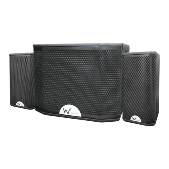
- Page 6 Make sure that the area below the installation place is blocked when rigging, derigging or servicing the system. Please note: W Audio cannot be made liable for damages caused by incorrect installations and excessive noise levels. Mid/top speaker Features: • Power handling nominal: 100W RMS • Efficiency (1watt/1metre): 93dB • Maximum calculated SPL: 116dB • Nominal impedance: 8 Ohms • Frequency response: (+/-3dB): 80Hz/125/200Hz - 20kHz (80Hz/125Hz, low cut) • Horizontal coverage: 90 degrees • Vertical coverage: 60 degrees • Low frequency transducer: 6.5”/165mm • High frequency transducer: 1”/25mm • Input connections: 1 x locking speaker socket • Pole mountable • Multiple rigging points: 2 x M6 (top) and 4 x M6 (rear) • Dimensions: 209 x 373 x 218mm (L x W x H) • Weight: 7Kgs Subwoofer features: • Power handling nominal: 400W RMS • Sub amplifier: 1 x 500W RMS @ 4 Ohms • Mid/top speaker amplifier: 2 x 150W RMS @ 8 Ohms • Efficiency (1watt/1metre): 95dB • Maximum SPL (1m): 125dB • Frequency response: (+/-3dB): 52Hz - 80Hz - 200Hz (hi cut 80Hz - 200Hz adjustable) • Low frequency transducer: 12”/300mm • Nominal impedance: 4 Ohms • Sub amplifier connections: 2 x locking speaker sockets • Mid/top speaker amplifier connections: 2 x XLR inputs, 2 x Jack mic inputs and 2 x XLR outputs • Pole mountable • Power supply: 240V • Dimensions: 470 x 360 x 490mm (L x W x H) • Weight: 25.5Kgs...
- Page 7 Overview: Mid/Top speaker: Sub amplifier:...
- Page 8 1. Satellite Input: Satellite input socket for speaker level signal input from the subwoofer. 2. Satellite Output: Speaker level signal output for connecting the Right satellite mid/high speaker. Minimum output impedance 8Ω 3. Microphone Inputs: Balanced 6.35mm (¼”) jack sockets for connection of dynamic microphones. 4. Microphone Gain Controls: Independent gain controls for each of the two microphone inputs 5. Phase Reverse: Switchable phase applicable to the subwoofer only. The phase reverse can be used to in certain venue’s where the room acoustics lead to phase cancellation as a result of subwoofer positioning and reflected waves. This may also be used to correct any reversed input wiring. The normal position for this switch should be the “Normal” position with the “Sub-Rev”...
- Page 9 18. Balanced Inputs: Stereo balanced line inputs suitable for input from a mixing console. If using the system in mono, only the left input should be used and the right output linked to the left input using a short, balanced XLR-XLR cable. 19. On/Off Switch: Mains power on/off for the system. Connections for signal input and speaker outputs must be made before powering on the system. 20. Earth Bond Point: This system must be earthed. The protective earth point is for test purpos- es only and must not be disconnected.
- Page 10 Balanced XLR Connection Connection With The Mains Connect the unit to the mains via the IEC mains inlet using the 13A UK - IEC cord supplied. The earth has to be connected. Switch the unit on. After switching on the speaker system, wait 8 - 10 seconds before you turn the volume control up in order to avoid speaker damage. CAUTION! Increase the level of each channel up to the point where the clip LEDs illuminate. Always check the sound pressure level with a meter in order to keep to the legal threshold. Connections This speaker system is equipped with 4 pole, lockable speaker sockets. For locking the connection turn the plug to the right. For unlocking pull the unlock button and turn the plug to the left and pull it out of the socket.
- Page 11 Installation Stacking This speaker system may only be installed on top of another speaker system if both systems are clamped up to each other via appropriate clamping belts and protected against tilting over. Satellite System The satellite system must always provide enough stability. The subwoofer’s base surface must always be sufficiently dimensioned in relation to the top speaker in order to prevent tilting over.
- Page 12 Installation on a Speaker Stand The speaker system may only be installed on a speaker stand if the original speaker system is equipped with an appropriate stand adaptor. Stands or satellite systems must only be installed on a plane area with a maximum inclination angle of 5˚. CAUTION: Speaker systems installed under the influence of horizontal forces, e.g.
- Page 13 Overhead Installation If the speaker system is to be installed with a mounting height of more than 1 meter (e.g. on a stage or framework), the speaker system must always be secured with an appropriate secondary secur- ing attachment. The installation must always be secured with a secondary safety attachment. e.g. an appropriate catch net. The secondary safety attachment must be constructed in a way that no part of the installation can fall down if the main attachment fails.
- Page 14 Secondary Attachment Please note: The Speaker system must always be secured with three appropriate eye bolts and three appropriate safety ropes. The eyelets and the safety ropes must always hold at least 12 times the weight of the speaker system. Please note: Before installing the eye bolts, make sure that the thread is is always in perfect condition and free from dirt. Install the eye bolts in the threaded holes on the speaker system. The eye bolts must be tightened until the stop position, hand tight with out any tools.
-
Page 15: Suspended Installation
Wall Installation The speaker system can only be installed on a wall, if the original speaker system is equipped with an appropriate mounting point. Before attaching the speaker system, make sure that the installation area can hold a minimum point load of 10 times the installations weight. - Page 16 Suspended Installation (cont...) Procedure Step 1: Unscrew the allen screw with a suitable allen key. Step 2: Install the eye bolts in the threaded holes on the speaker system. The eye bolts must be tightened until the stop position, hand tight without any tools. Step 3: Install the screw on chain link in the first and last links and tighten the fixation screw. Step 4: Install the chain with the screw on chain link at the installation eyelet of the ring coupler and tighten the fixation screw.
Need help?
Do you have a question about the SATURN 12 SYSTEM and is the answer not in the manual?
Questions and answers