Table of Contents
Advertisement
Quick Links
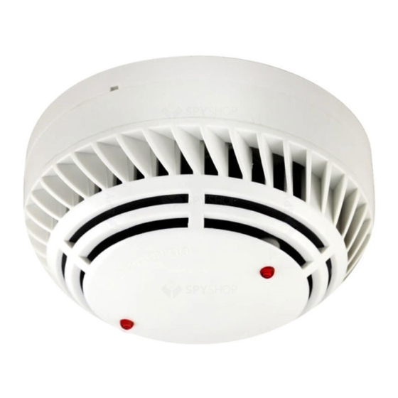
ZEOS-AD
Analogue Addressable Fire Detector
SUPPLY VOLTAGE
CURRENT - QUIESCENT / SURGE
CURRENT - DEVICE IN ALARM
SENSITIVITY
CABLE SIZE
RESET/START-UP TIMES
COLOUR / CASE MATERIAL / MAX. HUMIDITY
NORMAL / TRANSIENT OPER. TEMPERATURE
DIMENSIONS / WEIGHT
ORDER CODE
ZEOS-AD-S
ZEOS-AD-H
ZEOS-AD-SH
ZEOS-AD-SI
ZEOS-AD-HI
ZEOS-AD-SHI
INSTALLING THE BASE - To ensure proper fit of the detector head to the base, all wires should be properly dressed at installation by positioning all wires flat against terminals and
fastening the wires away from connector terminals. The detector base can be mounted directly onto most standard electrical junction boxes.
INSTALLING THE HEAD - Align detector components using provided alignment marks on both the head and base. Align detector mark and short alignment mark on base. Fit the
detector head onto the base and twist clockwise to secure it. After all detectors are installed, apply power to the control unit and activate the detection loop. Test the detectors
as described below.
TESTING - All remote signalling systems, releasing devices and extinguishing systems should be disconnected during the test period and reconnected at the conclusion of testing.
SMOKE: Allow smoke from a cotton wick or test smoke aerosol to enter the detector's smoke chamber for at least 10 seconds. When sufficient smoke has entered, the detector
will signal an alarm. This will be indicated by the illumination of the 2 Red LEDs provided. Make sure to clear smoke out of the chamber before resetting in order to keep the
detector at its current sensitivity setting.
HEAT: The detector to be tested should be subject to a flow of warm air at a temperature of between 65°C and 80°C. This requirement can be met by some domestic hair dryers.
Switch on the warm airflow and check that the temperature is correct and stable. From a distance of several cms, direct the airflow at the guard protecting the thermistor. The
detector should alarm within 60 seconds. Upon alarm immediately remove the heat source and check that the Red LEDs of the detector are illuminated. If a detector fails to
activate within 60 seconds, confirm connections and programming. If necessary replace unit. Note: After testing, check that the system is returned to normal operation. Notify
the appropriate authorities that the testing procedure has been completed and the system is active again.
MAINTENANCE - The recommended minimum requirement for detector maintenance consists of annual cleaning of dust from the detector head using a low power
>> DO NOT ATTEMPT TO DISASSEMBLE THE DETECTOR
vacuum cleaner.
NOTE: Positive terminal of remote indicator should be connected to terminal 4 (+ Loop IN/ OUT)
www.acornfiresecurity.com
TECHNICAL SPECIFICATIONS
Loop Powered - 17 V to 30 V DC
450 uA max.
4 mA - Alarm LED Iluminated
According to EN54-5 and EN54-7
0.5-2.5 mm²
20 seconds max.
White / ABS / 95% RH Non-Condensing
0°C to 50°C / -10°C to 85°C
100 mm (D) x 50 mm (H) inc. base / 144 g inc. base
| CERTIFICATE |
DESCRIPTION
1328-CPR-0521
ANALOGUE ADDRESSABLE PHOTOELECTRIC SMOKE DETECTOR
1328-CPR-0520
ANALOGUE ADDRESSABLE TEMPERATURE/HEAT DETECTOR
1328-CPR-0519
ANALOGUE ADDR. COMBINED SMOKE & HEAT DETECTOR
1328-CPR-0607
ANALOGUE ADDRESSABLE PHOTOELECTRIC SMOKE DETECTOR WITH ISOLATOR
1328-CPR-0610
ANALOGUE ADDRESSABLE TEMPERATURE/HEAT DETECTOR WITH ISOLATOR
1328-CPR-0492
ANALOGUE ADDR. COMBINED SMOKE & HEAT DETECTOR WITH ISOLATOR
INSTALLATION
DETECTOR BASE - LOOP CONNECTIONS
-Loop IN/ OUT
-Loop IN/ OUT
www.acornfiresecurity.com
ma_zeosad_01_010001_en_180420
Connection applicable only to:
ZEOS-AD-S / ZEOS-AD-H / ZEOS-AD-SH
- REMOTE LED INDICATOR
SCREEN
To next device
in loop or return
-Loop IN/ OUT
Connection applicable only to:
ZEOS-AD-SI / ZEOS-AD-HI / ZEOS-AD-SHI
+Loop IN/ OUT
MADE IN PORTUGAL - EU
to panel
Advertisement
Table of Contents

Subscribe to Our Youtube Channel
Related Manuals for Global Fire ZEOS-AD-S


Summary of Contents for Global Fire ZEOS-AD-S
- Page 1 >> DO NOT ATTEMPT TO DISASSEMBLE THE DETECTOR vacuum cleaner. DETECTOR BASE - LOOP CONNECTIONS -Loop IN/ OUT Connection applicable only to: ZEOS-AD-S / ZEOS-AD-H / ZEOS-AD-SH - REMOTE LED INDICATOR -Loop IN/ OUT SCREEN To next device in loop or return...
- Page 2 www.acornfiresecurity.com MECHANICAL SPECIFICATION Detector Head Alignment Marks Detector Base BASE LOCK To lock beacon remove pin To unlock beacon from its base available at terminal 4 on the push provided unlock key Address underside of the beacon using through hole available on the a small screwdriver.
Need help?
Do you have a question about the ZEOS-AD-S and is the answer not in the manual?
Questions and answers