
Related Manuals for Hanasis TEB-J1900A/P

Summary of Contents for Hanasis TEB-J1900A/P
- Page 1 TEB-J1900A/P Mother Board Manual Hanasis Mother Board (TEB-J1900A/P) User Manual Version 1.0 Published August 2017 Copyright©2017 Hanasis & Ruide All rights reserved 1 / 26...
- Page 2 (including damages for loss of profits, loss of business, loss of data, interruption of business and the like), even if Hanasis&Ruide has been advised of the possibility of such damages arising from any defect or error in the manual or product.
-
Page 3: Table Of Contents
TEB-J1900A/P Mother Board Manual Contents Chapter1 Introduction ---------------------------------------------------------------------------------------------- 4 1.1 Specification ------------------------------------------------------------------------------------------------------- 5 1.2 System Block Diagram ------------------------------------------------------------------------------------------- 6 1.3 Mother Board Layout --------------------------------------------------------------------------------------------- 7 1.4 I/O Panel Connector ---------------------------------------------------------------------------------------------- 7 Chapter2 Installation ----------------------------------------------------------------------------------------------- 9 2.1 Screw Holes -------------------------------------------------------------------------------------------------------- 9 2.2 Pre-Installation Precautions ------------------------------------------------------------------------------------- 9... -
Page 4: Chapter1 Introduction
Chapter1. Introduction Thank you for purchasing TEB-J1900 motherboard, a reliable motherboard produced under Hanasis&Ruide’s consistently stringent quality control. It delivers excellent performance with robust design conforming to Hanasis&Ruide’s commitment to quality and endurance. In this manual, chapter 1 and 2 contain introduction of the motherboard and step- by-step guide to the hardware installation. -
Page 5: Specification
TEB-J1900A/P Mother Board Manual 1.1 Specification Item Specification Hanasis Own Form Factor 6-Layer Form Factor Dimension Intel® Celeron Quad-Core Processor J1800 (2.41 GHz) / J1900 (2.0GHz) Socket FCBGA1170 Processor System 10 W BIOS AMI UEFI BIOS Speed & Type DDR3L 1600/1333MHz, Non-ECC & Un-buffered Memory... -
Page 6: System Block Diagram
TEB-J1900A/P Mother Board Manual 1.2 System Block Diagram 6 / 26... -
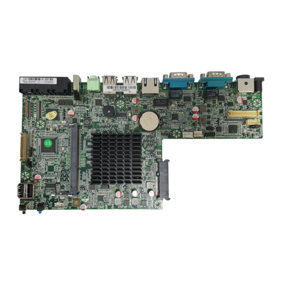
Page 7: Mother Board Layout
TEB-J1900A/P Mother Board Manual 1.3 Mother Board Layout (1) Touch Panel (16) LVDS (17) Back Light (18) Panel Power Jumper (2) LPT (12) CMOS Clear (11) Reset (3) USB2.0 (13) Debug (14) FAN (SYS) (4) AT/ATX Jumper (15) FAN (CPU) - Page 8 TEB-J1900A/P Mother Board Manual 1.4.1 LAN Port LED Indications There are two LED next to the LAN port. Please refer to the table below for the LAN port LED indications. Link LED Activity LED LAN JACK Status Description Status Description...
-
Page 9: Chapter2 Installation
TEB-J1900A/P Mother Board Manual Chapter2. Installation This is a Hanasis own form factor motherboard for POS system. Before you install the motherboard, study the configuration of your chassis to ensure that the motherboard fits into it. Make sure to unplug the power cord before installing or removing the motherboard. Failure to do so may cause physical injuries to you and damages to motherboard components. -
Page 10: Jumper Setup
TEB-J1900A/P Mother Board Manual 2.4 Jumper Setup The illustration shows how jumpers are setup. When the jumper cap is placed on pins, the jumper is “Short”. If no jumper cap is placed on pins, the jumper is “Open”. The illustration shows a 3-pin jumper whose pin1 and pin2 are “Short”... -
Page 11: Onboard Header And Connectors
TEB-J1900A/P Mother Board Manual 2.5 Onboard Header and Connectors 2.5.1 LVDS Connector (LVDS) Connector SPEC Shape Signal Description Remark 40-Pin 1.25 Pitch Refer to below Signal Description Signal Description +12V +12V +12V +12V +12V VCC 3.3V LVDS Panel PWR LVDS Panel PWR... - Page 12 TEB-J1900A/P Mother Board Manual 2.5.4 SYS FAN Connector (SYS_FAN) Connector SPEC Shape Signal Description Remark 1 : GND 3-Pin 2.5 Pitch 2 : +12V 3 : FAN Speed (Sense) 2.5.5 SATA-II Connector (SATA) Connector SPEC Shape Signal Description Remark 22-Pin SATA COMBO...
- Page 13 TEB-J1900A/P Mother Board Manual 2.6.10 Parallel Port Connector (JLPT) Connector SPEC Shape Signal Description Remark 26-Pin 2.0 Pitch Refer to below Signal Description Signal Description STB# AFD# SPD0 ERROR# SPD1 PINIT# SPD2 SLIN# SPD3 SPD4 SPD5 SPD6 SPD7 ACK# BUSY...
-
Page 14: I/O Connectors
TEB-J1900A/P Mother Board Manual 2.6 I/O Connectors 2.6.1 COM#1 / COM#2 Connector SPEC Shape Signal Description Remark DSUB 9Pin Refer to below Signal Description Signal Description COM Power 0V / 5V / 12V (Select by BIOS) NOTE] Pin9 of COM1/2 (DB9 on Rear IO) is 0V by default, +5V or +12V is selectable by setting BIOS. - Page 15 TEB-J1900A/P Mother Board Manual 2.6.4 LAN Connector SPEC Shape Signal Description Remark RJ-45 with LED Refer to below Signal Description Signal Description MD0 (+) MD2 (+) MD0 (-) MD2 (-) MD1 (+) MD3 (+) MD1 (-) MD3 (-) 2.6.5 HDMI...
-
Page 16: Chapter3 Bios Setup
TEB-J1900A/P Mother Board Manual Chapter3. BIOS SETUP 3.1 Access the BIOS Setup After power on, press the <Delete> Button during the P.O.S.T.(Power-on Self-Test) process. Once you enter the BIOS Setup, the Main Menu will show up on the screen, in which you can use the arrow keys to move or select the items, and press <Enter>... -
Page 17: Main Screen
TEB-J1900A/P Mother Board Manual 3.2 Main Screen This page contains the basic information about the BIOS version, and you can set the system date and time manually. 3.2.1 System Date Set the system date. The date format is [Week, Month/Day/Year]. Use <Tab> to switch the item between month, day and year. Ether you can use the <+>/<->... -
Page 18: Advanced Screen
TEB-J1900A/P Mother Board Manual 3.3 Advanced Screen In this section, you may set the configurations for the following items : ACPI Settings, Super IO Configuration, HW Monitor, CPU Configuration, PPM, IDE, CSM, Info Report, USB Configuration. Setting wrong values in this section may cause the system to malfunction. - Page 19 TEB-J1900A/P Mother Board Manual 3.3.2 Super IO Configuration 3.3.2.1 Serial Port1/2 Configuration This item is used to set parameters of COM1/2. COM1/2 support the serial port voltage to 5V or 12V by BIOS. 3.3.2.2 Serial Port3/4 Configuration This item is used to set parameters of COM3/4. COM3/4 support the serial port voltage to 5V by BIOS.
- Page 20 TEB-J1900A/P Mother Board Manual 3.3.4 CPU Configuration 3.3.4.1 Limit CPUID Maximum Use this item to enable or disable the maximum CPUID value limit, you can enable this item to prevent the system from “rebooting” when trying to install Windows NT 4.0.
- Page 21 TEB-J1900A/P Mother Board Manual 3.3.6 USB Configuration 3.3.6.1 Legacy USB Support Use this option to select legacy support for USB devices. There are four configuration options: [Enabled], [Auto] and [Disabled]. The default value is [Enabled]. Please refer to below descriptions for the details of these four options: [Enabled] - Enables support for legacy USB.
-
Page 22: Chipset Screen
TEB-J1900A/P Mother Board Manual 3.4 Chipset Screen 3.4.1 North-Bridge (Graphics Configuration / Memory Configuration) 3.4.1.1 DVMT Pre-Allocated This item is used to select DVMT 5.0 Pre-Allocated (Fixed) Graphics Memory size used by the Internal Graphics Device. 3.4.1.2 DVMT Total Gfx Mem This item shows the information of DVMT 5.0 and Graphic memory size used by the Internal Graphics Device. - Page 23 TEB-J1900A/P Mother Board Manual 3.4.1.9 Panel Scaling Set the way of panel scaling. 3.4.1.10 Backlight Control Set the way of controlling backlight. The default value is [PWM Normal]. 3.4.1.11 LCD Resolution Setting This item allows you to choose the proper resolution for your display device. The default value is [1024*768 (24Bit / 1-CH)].
-
Page 24: Security Screen
TEB-J1900A/P Mother Board Manual 3.5 Security Screen In this section, you may set, change or clear the supervisor/user password for the system. 3.5.1 Administrator Password This item allows you to configurate an administrator Password. Press <Enter> to creat a new password, type the password, then press <Enter>... -
Page 25: Boot Screen
TEB-J1900A/P Mother Board Manual 3.6 Boot Screen In this section, it will display the available devices on your system for you to configure the boot settings and the boot priority. 3.6.1 Setup Prompt Timeout This item is used to set number of seconds to wait for setup activation key. -
Page 26: Exit Screen
TEB-J1900A/P Mother Board Manual 3.7 Exit Screen 3.7.1 Save Changes and Exit This item enables you to exit system setup after saving the changes. 3.7.2 Discard Changes and Exit This item enables you to exit system setup without saving any changes.
Need help?
Do you have a question about the TEB-J1900A/P and is the answer not in the manual?
Questions and answers