Table of Contents
Advertisement
Available languages
Available languages
Quick Links
THE USER INTERFACE
The user has a display and four keys for
controlling status and programming of the
instrument.
KEYS AND MENUS
UP key
Scrolls through the menu items
Increases the values
DOWN key
Scrolls through the menu items
Decreases the values
FNC key
ESC function (exit)
fnc
SET key
Accesses the setpoint
set
Accesses the menus
Confirms the commands
out
IC901
At start-up the instrument performs a
Lamp Test; for few seconds the display and
the leds blink, in order to verify their
integrity and correct operation. The instru-
ment has two main menus: the "Machine
Status" and "Programming" menu.
ACCESSING AND USING MENUS
Resources are arranged in a menu, which
can be accessed by pressing and quickly
releasing the "set" key ("Machine Status"
menu) or by holding down the "set" key
for more than 5 seconds ("Programming"
menu).
To access the contents of each folder, indi-
cated by the relevant label, just press the
"set" key once.
You can now scroll through the contents
of each folder, modify it or use its func-
tions.
If you do not use the keyboard for over 15
seconds (time-out) or if you press the
"fnc" key once, the last value shown on
the display is confirmed and you return to
the previous screen mask.
LED
Position
Associated function
out
Relay 1
Alarm
°C
Setpoint
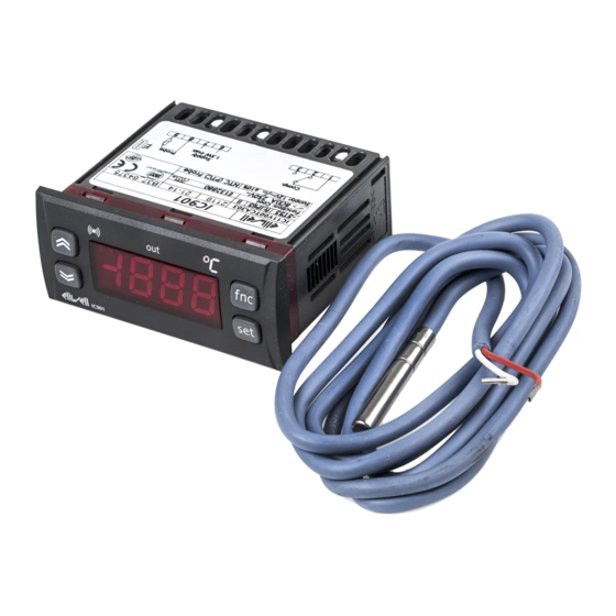
IC 901
electronic thermostat with single output
MACHINE STATUS MENU
(See Machine Status Menu)
To access the "Machine Status" menu Press
and quickly release the "set" key.
If alarms are not present, the label "SEt"
appears. By using the "UP" and "DOWN"
keys you can scroll through the other fold-
ers in the menu:
-Pb1: probe 1 value folder;
-SEt: Setpoint setting folder.
Set Setting
Access the "Machine Status" menu by
pressing and quickly releasing the "set"
key. The label of the "SEt" folder appears.
To display the Setpoint value press the
"set" key again.
The value appears on the display.
To change the Setpoint value, use the "UP"
and "DOWN" keys within 15 seconds.
If the parameter is LOC = y the Setpoint
cannot be changed.
Displaying Probes
f nc
By pressing the "set" key when the appro-
priate label appears, the value of the
set
probe associated to it is displayed.
PROGRAMMING MENU
(See Programming Menu)
To enter the "Programming" menu, press
the "set" key for more than 5 seconds.
If specified, the access PASSWORD will be
requested, (parameter "PA1"), and (if the
password is correct) the label of the first
folder will follow.
To scroll through the other folders, use
the "UP" and "DOWN" keys; the folders
contain the level 1 parameters.
If the password is wrong, the display will
show the PA1 label again.
To enter the folder, press "set". The label
of the first visible parameter appears. To
scroll through the other parameters, use
the "UP" and "DOWN" keys; to change the
parameter, press and release "set", then
set the desired value using the "UP" and
"DOWN" keys, and confirm with the "set"
key to move to the next parameter.
PLEASE NOTE: It is suggested to switch-off
and switch-on again the instrument every-
time it is changed the configuration of the
parameters: this prevents malfunctioning
on regulation and delay time occuring.
Status
ON for relay ON, flashing for delay, disabled protection
or activation
ON for an active alarm
ON when setting the Setpoint
PASSWORD
The password "PA1"allow access to level 1
parameters. In the standard configuration
passwords are not present.
To enable them (value≠0) and assign them
the desired value, access the
"Programming" menu, within the folder
with the "diS" label.
If password is enabled, it will be request-
ed at the entrance of the "Programming"
menu (see the "Programming Menu" sec-
tion);
COPY CARD
The Copy Card is an accessory connected
to the TTL serial port which allows pro-
gramming quickly the instrument parame-
ters. The operation is performed as fol-
lows:
Upload
This operation loads the programming
parameters from the instrument.
Download
This operation downloads to the instru-
ment the programming parameters.
The operations are performed accessing
the folder identified by the "FPr" label and
selecting, according to the case, "UL" or
"dL" commands; the operation is con-
firmed by pressing the "set" key. If the
operation is successful an "y" is displayed,
on the contrary, if it fails a "n" will be dis-
played.
NOTE:
• UPLOAD: instrument --> Copy Card
• DOWNLOAD: Copy Card --> instru-
ment.
KEYBOARD LOCKING
The instrument includes a facility for dis-
abling the keyboard, by programming the
"Loc" parameter (see folder with "Dis"
label). If the keyboard is locked, you can
still access the programming menu by
pressing the "set" key.
The Setpoint can also be viewed.
DIAGNOSTICS
The alarm condition is always signalled by
the buzzer (if present) and by the led of
the alarm icon
The alarm signal produced by a faulty
thermostat probe (probe 1) is shown as E1
on the instrument display.
Error table
DISPLAY
ERROR
E1
Thermostat probe fault
Advertisement
Table of Contents

Subscribe to Our Youtube Channel
Related Manuals for Eliwell IC 901


Summary of Contents for Eliwell IC 901
- Page 1 IC 901 electronic thermostat with single output THE USER INTERFACE MACHINE STATUS MENU PASSWORD (See Machine Status Menu) The password “PA1”allow access to level 1 The user has a display and four keys for To access the “Machine Status” menu Press parameters.
-
Page 2: Installation
Invensys for example, sensors. Controls Italy s.r.l. reserves the right to This means, for example, that sensor(s) make any changes or improvements with- error(s) shall be added to the instru- out prior notice. ment’s one. IC 901... - Page 3 • It is strongly recommended, anyway to switch off and switch on again the controller anytime parameters have been changed to prevent malfunctioning on configuration and/or ongoing timings SEt value press and release (single press) change SEt value Pb1 value Machine Status Menu Diagram IC 901...
- Page 4 Wiring diagram WIRING (12 and 230V) 1 - 2 N.C. regulator relay output OUT IC 901 - 12 V 1 - 3 N.O. regulator relay output OUT 6 - 7 Power supply • model 230V: 3 VA max.
-
Page 5: Interfaccia Utente
IC 901 termostato elettronico ad 1 gradino INTERFACCIA UTENTE Non agendo sulla tastiera per più di 15 parametri usare i tasti “UP” e “DOWN”, secondi (time-out) o premendo una volta per modificare il parametro premere e L’utente dispone di un display e di quattro il tasto “fnc”, viene confermato l’ultimo... -
Page 6: Declinazione Di Responsabilità
- uso su quadri che permettono l’accesso a Ciò implica, ad esempio, che l’errore un fusibile da 250 mA ritardato. parti pericolose senza l’uso di utensili; introdotto dalla sonda va a aggiungersi - manomissione e/o alterazione del pro- a quello caratteristico dello strumento. IC 901... - Page 7 • E’ consigliato spegnere e riaccendere lo strumento ogniqualvolta si modifichi la configurazione dei parametri per prevenire malfunzionamenti sulla configurazione e/o temporizzazioni in corso. valore SEt premere e rilasciare (istantaneamente/ cambia valore singola pressione) valore Pb1 Schema Menu Stato Macchina IC 901...
- Page 8 Schema di Collegamento MORSETTI (modelli 12 e 230V) 1 - 2 N.C. relè regolatore OUT IC 901 - 12 V 1 - 3 N.A. relè regolatore OUT 6 - 7 Alimentazione • modello 230V: 3 VA max.
-
Page 9: Interfaz Usuario
IC 901 termostato electrónico de 1 punto de intervención INTERFAZ USUARIO se por el contenido de cada una de las car- interior de la carpeta pulse “set”. Aparece petas, modificarlo o utilizar las funciones la etiqueta del primer parámetro visible. -
Page 10: Montaje Mecánico
250 mA - la utilización en cuadros que permiten retardado. acceder a piezas peligrosas sin la utilización La sonda no se caracteriza por ninguna de herramientas; polaridad de inserción y puede prolongarse - el manejo inexperto y/o alteración del IC 901... - Page 11 Esto significa, por ejemplo, que el error causado por la sonda se añade al caracterís- tico del instrumento. valor SEt pulsar y soltar (instantáneamente/ cambia valor una sola vez) valor Pb1 Esquema Menú Estado de la máquina IC 901...
- Page 12 Esquema de Conexión BORNES (12 y 230V) 1 - 2 N.C. relé regulador OUT IC 901 - 12 V 1 - 3 N.A. relé regulador OUT 6 - 7 Alimentación • modelo 230V: 3 VA máx.
- Page 13 IC 901 Temperaturregler 1 Ausgang BENUTZERSCHNITTSTELLE einer jeden Registerkarten durchzusehen, Display erneut das Label PA1 an. zu ändern oder die darin vorgesehenen Zum Durchgehen der übrigen Der Benutzer verfügt über einen Display Funktionen zu benutzen. Registerkarten die Tasten „UP“ und sowie vier Tasten für die Steuerung des Status...
-
Page 14: Mechanische Montage
Das Instrument weist eine Menschenverstand aufgrund von Schraubklemmleiste für den Anschluss der Sicherheitserfordernissen vorschreibt, müs- elektrischen Kabel mit einem max. sen außerhalb des Instruments realisiert Querschnitt von max. 2,5 mm auf (nur ein werden. IC 901... - Page 15 Controls Italy S.r.l. keinerlei Verantwortung für die mit ihr verbundene Benutzung. Gleiches gilt für Personen oder Firmen, die bei der Abfassung des Handbuchs mitgewirkt haben.Invensys Controls Italy S.r.l. behält sich das Recht vor, jederzeit und ohne vorherige Ankündigung, Änderungen funktioneller oder ästhetischer Art sowie Verbesserungen vorzunehmen. DRÜCKEN UND SOLLWERT AUFLOCKEN (SEt) WERT (SEt) (EINMAL DRÜCKEN) EINSTELLEN Pb1 WERT Programmierung Menü Schema IC 901...
- Page 16 Duty Cycle programmiert, oder: Anschluss-Plan KLEMMEN (12 und 230V) 1 - 2 N.C. Relais Regler OUT IC 901 - 12 V 1 - 3 N.O. Relais Regler OUT 6 - 7 Speisung • Modell 230V: 3 VA max.
-
Page 17: Face Avant
IC 901 Thermostat avec affichage, 1 sortie relais FACE AVANT pour accéder au contenu de chaque sous- agir sur les touches "UP" et "DOWN". menu, mis en évidence par l’étiquette cor- Pour entrer à l'intérieur du sous menu, L'utilisateur dispose d'un afficheur et de respondante, il suffit d'appuyer une fois appuyer sur "set"... -
Page 18: Branchements Electriques
élec- des relais et alimentations. d'un fusible de 250 mA retardé. triques, l'eau et la poussière dans les Les sondes ne sont caractérisées par aucu- conditions de montage habituelles ; IC 901... - Page 19 •NOTE: Il est conseillé d’éteindre et ré allumer le régulateur chaque fois que les paramètres seront modifiés! APPUYER 5 sec Schéma Menu de Programmation PA1≠0 MODIFIER Par niveau 1 Par niveau 1 DEFILER PARAMETRES MODIFIER Par niveau 1 VALEUR PARAMÈTRES répertoire niveau 1 Par niveau 1 niveau 1 IC 901...
- Page 20 1 - 2 N.F. relais régulateur OUT 1 - 3 N.O. relais régulateur OUT IC 901 - 12 V 6 - 7 Alimentation • modèle 230V : 3 VA max. • modèle 12V : 1,5 VA max. 8 - 9 Entrée sonde 1 (thermostation) Pb1...
Need help?
Do you have a question about the IC 901 and is the answer not in the manual?
Questions and answers