Advertisement
Quick Links
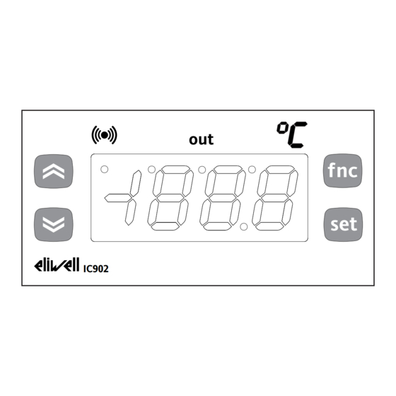
THE USER INTERFACE
The user has a display and four keys for
controlling status and programming of the
instrument.
KEYS AND MENUS
UP key
Scrolls through the menu items
Increases the values
DOWN key
Scrolls through the menu items
Decreases the values
fnc key
ESC function (exit)
fnc
set key
Accesses the setpoint
set
Accesses the menus
Confirms the commands
out
IC902
At start-up the instrument performs a
Lamp Test; for few seconds the display and
the leds blink, in order to verify their
integrity and correct operation. The instru-
ment has two main menus: the "Machine
Status" and "Programming" menu.
ACCESSING AND USING MENUS
Resources are arranged in a menu, which
can be accessed by pressing and quickly
releasing the "set" key ("Machine Status"
menu) or by holding down the "set" key
for more than 5 seconds ("Programming"
menu).
To access the contents of each folder, indi-
cated by the relevant label, just press the
"set" key once.
You can now scroll through the contents
of each folder, modify it or use its func-
tions.
If you do not use the keyboard for over 15
seconds (time-out) or if you press the
"fnc" key once, the last value shown on
the display is confirmed and you return to
the previous screen mask.
LED
Position
Associated function
out
Relay 1
Alarm
°C
Setpoint
IC 902
electronic thermostat with single output
MACHINE STATUS MENU
(See Machine Status Menu)
To access the "Machine Status" menu Press
and quickly release the "set" key.
If alarms are not present, the label "SEt"
appears. By using the "UP" and "DOWN"
keys you can scroll through the other fold-
ers in the menu:
-Pb1: probe 1 value folder;
-SEt: Setpoint setting folder.
Set Setting
Access the "Machine Status" menu by
pressing and quickly releasing the "set"
key. The label of the "SEt" folder appears.
To display the Setpoint value press the
"set" key again.
The value appears on the display.
To change the Setpoint value, use the "UP"
and "DOWN" keys within 15 seconds.
If the parameter is LOC = y the Setpoint
cannot be changed.
Displaying Probes
f nc
By pressing the "set" key when the appro-
priate label appears, the value of the
set
probe associated to it is displayed.
PROGRAMMING MENU
(See Programming Menu)
To enter the "Programming" menu, press
the "set" key for more than 5 seconds.
If specified, the access PASSWORD will be
requested, (parameter "PA1"), and (if the
password is correct) the label of the first
folder will follow.
To scroll through the other folders, use
the "UP" and "DOWN" keys; the folders
contain the level 1 parameters.
If the password is wrong, the display will
show the PA1 label again.
To enter the folder, press "set". The label
of the first visible parameter appears. To
scroll through the other parameters, use
the "UP" and "DOWN" keys; to change the
parameter, press and release "set", then
set the desired value using the "UP" and
"DOWN" keys, and confirm with the "set"
key to move to the next parameter.
PLEASE NOTE: It is suggested to switch-off
and switch-on again the instrument every-
time it is changed the configuration of the
parameters: this prevents malfunctioning
on regulation and delay time occuring.
Status
ON for relay ON, flashing for delay, disabled protection
or activation
ON for an active alarm
ON when setting the Setpoint
PASSWORD
The password "PA1"allow access to level 1
parameters. In the standard configuration
passwords are not present.
To enable them (value≠0) and assign them
the desired value, access the
"Programming" menu, within the folder
with the "diS" label.
If password is enabled, it will be request-
ed at the entrance of the "Programming"
menu (see the "Programming Menu" sec-
tion);
COPY CARD
The Copy Card is an accessory connected
to the TTL serial port which allows pro-
gramming quickly the instrument parame-
ters. The operation is performed as fol-
lows:
Upload
This operation loads the programming
parameters from the instrument.
Download
This operation downloads to the instru-
ment the programming parameters.
The operations are performed accessing
the folder identified by the "FPr" label and
selecting, according to the case, "UL" or
"dL" commands; the operation is con-
firmed by pressing the "set" key. If the
operation is successful an "y" is displayed,
on the contrary, if it fails a "n" will be dis-
played.
NOTE:
• UPLOAD: instrument --> Copy Card
• DOWNLOAD: Copy Card --> instru-
ment.
KEYBOARD LOCKING
The instrument includes a facility for dis-
abling the keyboard, by programming the
"Loc" parameter (see folder with "Dis"
label). If the keyboard is locked, you can
still access the programming menu by
pressing the "set" key.
The Setpoint can also be viewed.
DIAGNOSTICS
The alarm condition is always signalled by
the buzzer (if present) and by the led of
the alarm icon
The alarm signal produced by a faulty
thermostat probe (probe 1) is shown as E1
on the instrument display.
Error table
DISPLAY
ERROR
E1
Thermostat probe fault
Advertisement

Related Manuals for Eliwell ic 902


Summary of Contents for Eliwell ic 902
- Page 1 IC 902 electronic thermostat with single output THE USER INTERFACE MACHINE STATUS MENU PASSWORD (See Machine Status Menu) The password “PA1”allow access to level 1 The user has a display and four keys for To access the “Machine Status” menu Press parameters.
-
Page 2: Technical Data
Invensys for example, sensors. Controls Italy s.r.l. reserves the right to This means, for example, that sensor(s) make any changes or improvements with- error(s) shall be added to the instru- out prior notice. ment’s one. IC 902... - Page 3 • It is strongly recommended, anyway to switch off and switch on again the controller anytime parameters have been changed to prevent malfunctioning on configuration and/or ongoing timings SEt value press and release (single press) change SEt value Pb1 value Machine Status Menu Diagram IC 902...
- Page 4 Wiring diagram WIRING (12 and 230V) 1 - 2 N.C. regulator relay output OUT IC 902 - 12 V 1 - 3 N.O. regulator relay output OUT 6 - 7 Power supply • model 230V: 3 VA max.
Need help?
Do you have a question about the ic 902 and is the answer not in the manual?
Questions and answers
how to set 4 degree Celsius off turn on at 8 degree Celsius
To set the Eliwell IC 902 thermostat to turn on at 8°C and off at 4°C, follow these steps:
1. Access the Setpoint (SEt) Menu:
- Press and quickly release the "set" key.
- Use the “UP” and “DOWN” keys to navigate to the SEt folder.
- Press “set” again to enter the setpoint adjustment.
2. Set the Setpoint Value (SEt) to 4°C:
- Use the “UP” and “DOWN” keys to set the value to 4°C.
- Press “set” to confirm.
3. Adjust the Differential (diF) Value:
- Access the Programming Menu.
- Navigate to the diF parameter.
- Set the differential to 4°C (since 4°C + 4°C = 8°C).
- Confirm and exit.
This configuration ensures the thermostat turns off at 4°C and restarts when the temperature reaches 8°C.
This answer is automatically generated