Table of Contents
Advertisement
Quick Links
Advertisement
Table of Contents

Related Manuals for Slerj SSR-1U

Summary of Contents for Slerj SSR-1U
- Page 1 SSR-1U User’s Manual Revision - 27 December 2019...
-
Page 2: Table Of Contents
Features ..........................4 Getting Started ......................... 4 Package Contents ......................4 The SSR-1U Hardware..................... 5 Part Numbers ........................6 Connecting the SSR-1U ....................7 Using the SSR-1U ......................10 Functional Overview ......................11 Serial Channels ....................... 11 Record Function ......................11 User Interface Module .................... - Page 3 Slerj, shipping prepaid, for prompt repair or replacement. Slerj, its suppliers, and its licensors shall in no event be liable for any damages arising from the use of or inability to use this product. This includes business interruption, loss of business information, or other loss which may arise from the use of this product.
-
Page 4: Introduction
1 Introduction 1.1 Description The SSR-1U is a flexible and robust serial data recording device that takes care of the details of storing data so that you can focus on your application. Up to four streams of serial data can be recorded simultaneously, and each channel is configurable with a variety of serial and storage options. -
Page 5: The Ssr-1U Hardware
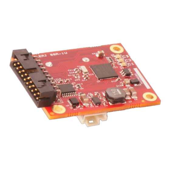
SSR-1U User’s Manual Rev -, 27 Dec 2019 2.2 The SSR-1U Hardware Main Connector Channel Status LEDs Insert card as shown in slot beneath board. Figure 1. Top View Aux connector (USB and Channel 4) microSD Card Slot (push-push type connector) -
Page 6: Part Numbers
SSR-1U User’s Manual Rev -, 27 Dec 2019 WARNING: Improper removal of the backup battery can damage the SSR-1U. To remove the battery, use a blunt stick to push the battery out of the holder. DO NOT PRY OR PULL THE BATTERY. -
Page 7: Connecting The Ssr-1U
Figure 4 and described in Table 2. The default configuration of the SSR-1U provides access to the user shell (see Section 4 Interactive Shell, for details) on channel 4 (aux connector) and causes channels 1, 2 and 3 to record when the digital input command pin (DI, pin 15) is pulled to ground. - Page 8 5V tolerant, TTL compatible, 3.3V CMOS input. Active polarity is configurable using the Interactive Shell. The SSR-1U has onboard diodes to allow power from either the main or aux connector, and both can be applied simultaneously without damage to the device. It is not necessary to supply 5V on pin 8 to access USB if power is supplied at the main connector.
- Page 9 SSR-1U User’s Manual Rev -, 27 Dec 2019 Figure 5. Typical application wiring using the default SSR-1U configuration © 2019 Slerj, LLC www.slerj.com...
-
Page 10: Using The Ssr-1U
Rev -, 27 Dec 2019 2.5 Using the SSR-1U The SSR-1U default configuration sets all channels to 115200 baud, 8 data bits, no parity, and 1 stop bit. Channels 1-3 are configured to record when DI is pulled low. Channel 4 is configured to present the user shell. -
Page 11: Functional Overview
Rev -, 27 Dec 2019 3 Functional Overview The SSR-1U consists of four asynchronous serial channels, a data recording subsystem, a user interface module, a real-time clock, digital input/output for status and control, and a USB interface for accessing microSD card data as a mass storage device. - Page 12 (interactive shell or control protocol). File Type The SSR-1U supports three archive types: raw, tagged line, and time tagged archives. o When file type is raw, bytes are written to file just as they are received, and no timestamp information is attached to the data.
- Page 13 Supported file creation modes are retry, overwrite, and append. When file mode is retry, the SSR-1U will continue to retry the file creation operation until it succeeds. File creation can fail if a file with the same name already exists. This mode is a useful complement to user definable file paths (next bullet).
-
Page 14: User Interface Module
File Size The SSR-1U supports automatic file close and reopen when a size (or time) threshold is reached. Threshold values of 1 MB, 2 MB, 4 MB, 8 MB, 16 MB, 32 MB, 64 MB, 128 MB, 256 MB, 512 MB, and 1024 MB are supported. Additionally, the File Size parameter can be set to Hour, Day, or Week, causing new files to be started based on time instead of size. -
Page 15: Usb Interface
In addition to the standard USB connections (two data signals, 5V power, and ground), a USB Enable pin (UEN) is provided for flexibility. The SSR-1U can be powered from the USB interface without enabling USB access to the card. Options for UEN control are detailed with the config usben command in Section 4.3 Device Configuration. -
Page 16: Interactive Shell
SSR-1U User’s Manual Rev -, 27 Dec 2019 4 Interactive Shell The interactive shell is designed to provide easy access to the SD card file system, device status, and configuration options. Entering ‘?’ or ‘help’ at the command prompt provides information about using the shell. -
Page 17: System Commands
SSR-1U User’s Manual Rev -, 27 Dec 2019 4.1 System Commands System commands provide access to general system functions including the real time clock and operational status. Table 6. System Commands Command Aliases Description clear Clears the screen. date [yyyymmdd] Sets the current date to the year, month, and day specified. -
Page 18: Device Configuration
(RAM) and can be saved to non-volatile memory for preservation across resets. On startup, if the contents of the non-volatile configuration memory are valid, the stored configuration is loaded and used by the SSR-1U. The shell provides access to device configuration through the following commands: Table 8. -
Page 19: Capturing The Shell
SSR-1U User’s Manual Rev -, 27 Dec 2019 Table 9. Channel Configuration Commands Command Alias Description baud <rate> Sets baud to rate (600 to 115200). bits {8 | 7} Sets data bits to 8 or 7. parity { E | O | N | e | o | n } Sets parity to even, odd, or none. - Page 20 When the previous step has been completed, the SSR-1U will send a random challenge string consisting of 4 upper case characters, and a new capture window of 5 seconds is established.
-
Page 21: Control Protocol
AND logical operation. 5.1 Message Format Control protocol messages are exchanged between the SSR-1U and the user in the form of byte- oriented packets. Each packet has a start sequence, an ID, a payload count, an optional payload, and a checksum. -
Page 22: General Messages
General messages (Table 12) provide access to command functions and status of the SSR-1U. All general messages received by the SSR-1U will be answered with a message to acknowledge (ACK), to negatively acknowledge (NACK), or to provide the requested data. - Page 23 All general output messages (direction = out) must be polled by the user. A message is polled by sending a message to the SSR-1U with the same message ID and zero payload. For example, to poll the All Channel Status message (ID = 0x24), construct the poll message as follows:...
- Page 24 SSR-1U User’s Manual Rev -, 27 Dec 2019 5.2.1 Record Record Message Requests recording to start immediately on the specified channel. Description Payload Length Direction Message Rate 0x10 1 to 45 bytes Payload Byte Type Notes Name Units Purpose / Comment Offset Channel (1 –...
- Page 25 SSR-1U User’s Manual Rev -, 27 Dec 2019 5.2.2 Stop Stop Message Requests the specified channel to stop recording immediately. Description Payload Length Direction Message Rate 0x11 1 byte Payload Byte Type Notes Name Units Purpose / Comment Offset Channel (1 – 4)
- Page 26 SSR-1U User’s Manual Rev -, 27 Dec 2019 5.2.4 Card Status Card Status Message Provides the status of the SD card as detected by the socket. Description Payload Length Direction Message Rate 0x21 1 byte polled Payload Byte Type Notes...
- Page 27 SSR-1U User’s Manual Rev -, 27 Dec 2019 5.2.6 All Channel Status All Channel Status Message Provides the status of all channels. Description Payload Length Direction Message Rate 0x24 4 bytes polled Payload Byte Type Notes Name Units Purpose / Comment...
- Page 28 SSR-1U User’s Manual Rev -, 27 Dec 2019 5.2.7 Set Date Set Date Message Sets the date. Description Payload Length Direction Message Rate 0x30 4 bytes Payload Byte Type Notes Name Units Purpose / Comment Offset Year (2001 – 2099) year Month (1 –...
- Page 29 SSR-1U User’s Manual Rev -, 27 Dec 2019 5.2.9 Set Time Set Time Message Sets the time. Description Payload Length Direction Message Rate 0x31 3 bytes Payload Byte Type Notes Name Units Purpose / Comment Offset Hour (0 – 23) hour Minute (1 –...
- Page 30 SSR-1U User’s Manual Rev -, 27 Dec 2019 5.2.11 Configuration Set Configuration Set Message Provides access to configuration functions. Description Payload Length Direction Message Rate 0x50 > 1 bytes Payload Byte Type Notes Name Units Purpose / Comment Offset payload...
- Page 31 SSR-1U User’s Manual Rev -, 27 Dec 2019 5.2.13 Reset Reset Message Resets the SSR-1U. Description Payload Length Direction Message Rate 0x99 0 bytes Notes: Possible Replies: NACK_INV_LEN © 2019 Slerj, LLC www.slerj.com...
-
Page 32: Configuration Messages
Rev -, 27 Dec 2019 5.3 Configuration Messages The Control Protocol provides a packetized interface to the configuration of the SSR-1U. Operations are the same as those available through the shell. For an overview of configuring the SSR-1U, refer to Section 4.3 Device Configuration. The control protocol provides access to configuration through the Configuration Set and Configuration Query messages. - Page 33 SSR-1U User’s Manual Rev -, 27 Dec 2019 5.3.1 Load Load Configuration Request Loads the configuration data stored in non-volatile configuration memory. Description Configuration Set Message Container Configuration ID Payload Length Direction 0x01 1 bytes Payload Byte Type Notes Name...
- Page 34 SSR-1U User’s Manual Rev -, 27 Dec 2019 5.3.3 Erase Erase Configuration Request Erases the non-volatile configuration memory. Description Configuration Set Message Container Configuration ID Payload Length Direction 0x03 1 bytes Payload Byte Type Notes Name Units Purpose / Comment...
- Page 35 SSR-1U User’s Manual Rev -, 27 Dec 2019 5.3.4 Set Channel Parameter 5.3.4.1 Line Set Line Request Sets all communication parameters of a channel. Description Container Configuration Set Message Configuration ID Payload Length Direction 0x10 5 bytes Payload Byte Type...
- Page 36 SSR-1U User’s Manual Rev -, 27 Dec 2019 5.3.4.2 Baud Set Baud Request Sets baud rate for a channel. Description Configuration Set Message Container Configuration ID Payload Length Direction 0x11 4 bytes Payload Byte Type Notes Name Units Purpose / Comment...
- Page 37 SSR-1U User’s Manual Rev -, 27 Dec 2019 5.3.4.3 Parity Set Parity Request Sets parity for a channel. Description Configuration Set Message Container Configuration ID Payload Length Direction 0x12 3 bytes Payload Byte Type Notes Name Units Purpose / Comment...
- Page 38 SSR-1U User’s Manual Rev -, 27 Dec 2019 5.3.4.4 Stop Set Stop Request Sets stop bits for a channel. Description Configuration Set Message Container Configuration ID Payload Length Direction 0x13 3 bytes Payload Byte Type Notes Name Units Purpose / Comment...
- Page 39 SSR-1U User’s Manual Rev -, 27 Dec 2019 5.3.4.5 Data Bits Set Data Bits Request Sets data bits for a channel. Description Configuration Set Message Container Configuration ID Payload Length Direction 0x14 3 bytes Payload Byte Type Notes Name Units...
- Page 40 SSR-1U User’s Manual Rev -, 27 Dec 2019 5.3.4.6 Function Set Function Request Sets a channel’s function. Description Configuration Set Message Container Configuration ID Payload Length Direction 0x20 3 bytes Payload Byte Type Notes Name Units Purpose / Comment Offset Configuration ID Channel (1 –...
- Page 41 SSR-1U User’s Manual Rev -, 27 Dec 2019 5.3.4.7 Source Set Source Request Sets a channel’s record command source. Description Configuration Set Message Container Configuration ID Payload Length Direction 0x21 3 bytes Payload Byte Type Notes Name Units Purpose / Comment...
- Page 42 SSR-1U User’s Manual Rev -, 27 Dec 2019 5.3.4.8 Soft Command Set Soft Command Request Sets the value of a channel’s internal soft command. Description Configuration Set Message Container Configuration ID Payload Length Direction 0x22 3 bytes Payload Byte Type...
- Page 43 SSR-1U User’s Manual Rev -, 27 Dec 2019 5.3.4.9 File Type Set File Type Request Sets the type of archive that a channel will record (raw or time tagged). Description Configuration Set Message Container Configuration ID Payload Length Direction 0x30...
- Page 44 SSR-1U User’s Manual Rev -, 27 Dec 2019 5.3.4.10 File Mode Set File Mode Request Sets the file open mode used by a channel. Description Configuration Set Message Container Configuration ID Payload Length Direction 0x31 3 bytes Payload Byte Type...
- Page 45 SSR-1U User’s Manual Rev -, 27 Dec 2019 5.3.4.11 File Path Set File Path Request Sets the path template used by a channel when recording. Description Configuration Set Message Container Configuration ID Payload Length Direction 0x33 3 to 46 bytes...
- Page 46 SSR-1U User’s Manual Rev -, 27 Dec 2019 5.3.4.12 File Size Set File Size Request Sets the file size threshold used by a channel. Description Configuration Set Message Container Configuration ID Payload Length Direction 0x34 3 bytes Payload Byte Type...
- Page 47 5.3.5 Query Channel Parameter Queries to the configuration subsystem are performed using Configuration Query messages. When a valid query is received, the SSR-1U replies with a Configuration Query Reply. Configuration Reply uses the same message ID (0x51) as the Configuration Query. The payload of the reply depends on the request, and available configuration items are listed below.
- Page 48 SSR-1U User’s Manual Rev -, 27 Dec 2019 5.3.5.2 Baud Baud Item Provides baud rate for a channel. Description Configuration Query Reply Message Container Configuration ID Payload Length Direction Message Rate 0x11 4 bytes polled Payload Byte Type Notes Name...
- Page 49 SSR-1U User’s Manual Rev -, 27 Dec 2019 5.3.5.3 Parity Parity Item Provides parity for a channel. Description Configuration Query Reply Message Container Configuration ID Payload Length Direction Message Rate 0x12 3 bytes polled Payload Byte Type Notes Name Units...
- Page 50 SSR-1U User’s Manual Rev -, 27 Dec 2019 5.3.5.4 Stop Stop Item Provides stop bits for a channel. Description Configuration Query Reply Message Container Configuration ID Payload Length Direction Message Rate 0x13 3 bytes polled Payload Byte Type Notes Name...
- Page 51 SSR-1U User’s Manual Rev -, 27 Dec 2019 5.3.5.5 Data Bits Data Bits Item Provides data bits for a channel. Description Configuration Query Reply Message Container Configuration ID Payload Length Direction Message Rate 0x14 3 bytes polled Payload Byte Type...
- Page 52 SSR-1U User’s Manual Rev -, 27 Dec 2019 5.3.5.6 Function Function Item Provides a channel’s function. Description Configuration Query Reply Message Container Configuration ID Payload Length Direction Message Rate 0x20 3 bytes polled Payload Byte Type Notes Name Units Purpose / Comment...
- Page 53 SSR-1U User’s Manual Rev -, 27 Dec 2019 5.3.5.7 Source Source Item Provides a channel’s record command source. Description Configuration Query Reply Message Container Configuration ID Payload Length Direction Message Rate 0x21 3 bytes polled Payload Byte Type Notes Name...
- Page 54 SSR-1U User’s Manual Rev -, 27 Dec 2019 5.3.5.8 Soft Command Soft Command Item Provides the value of a channel’s internal soft command. Description Configuration Query Reply Message Container Configuration ID Payload Length Direction Message Rate 0x22 3 bytes polled...
- Page 55 SSR-1U User’s Manual Rev -, 27 Dec 2019 5.3.5.9 File Type File Type Item Provides the type of archive that a channel will record (raw or time tagged). Description Configuration Query Reply Message Container Configuration ID Payload Length Direction Message Rate...
- Page 56 SSR-1U User’s Manual Rev -, 27 Dec 2019 5.3.5.10 File Mode File Mode Item Provides the file open mode used by a channel. Description Configuration Query Reply Message Container Configuration ID Payload Length Direction Message Rate 0x31 3 bytes polled...
- Page 57 SSR-1U User’s Manual Rev -, 27 Dec 2019 5.3.5.11 File Path File Path Item Provides the path template used by a channel when recording. Description Configuration Query Reply Message Container Configuration ID Payload Length Direction Message Rate 0x33 3 to 46 bytes...
- Page 58 SSR-1U User’s Manual Rev -, 27 Dec 2019 5.3.5.12 File Size File Size Item Provides the file size threshold used by a channel. Description Configuration Query Reply Message Container Configuration ID Payload Length Direction Message Rate 0x34 3 bytes polled...
-
Page 59: Error Codes
SSR-1U User’s Manual Rev -, 27 Dec 2019 5.4 Error Codes The control protocol provides a unified set of error codes to simplify interpreting and displaying errors to the user. The possible error codes are listed in Table 13. Table 13. Control Protocol Error Codes... -
Page 60: Time Tagged Archives
All multi-byte words in the archive are big endian. Note that a software utility, including source code, is provided with the SSR-1U for parsing time tagged archives into a variety of useful formats. See section 6.3 The STTP Utility for details. -
Page 61: Time Correlation Packet
SSR-1U User’s Manual Rev -, 27 Dec 2019 6.2 Time Correlation Packet The time correlation packet associates the free running clock timer with the real time clock. A time correlation packet is written when the recording is started, every 10 minutes, and as the recording is stopped. -
Page 62: The Sttp Utility
The SLERJ Time Tagged Parser is a Windows command line utility (sttp.exe) provided with the SSR-1U to parse time tagged archives into various output types. Source code is provided under a non-restrictive (MIT) license so that it can be freely modified and incorporated into user applications. - Page 63 SSR-1U User’s Manual Rev -, 27 Dec 2019 Extracting this data with options -n outputfile.txt -N "%m/%d/%Y %H:%M:%S." would produce an output file: 02/03/2014 21:47:38.915 S D 0.0000122 kg 02/03/2014 21:47:39.013 S D 0.0000122 kg 02/03/2014 21:47:39.111 S D 0.0000122 kg 02/03/2014 21:47:39.207 S D...
-
Page 64: Specifications
SSR-1U User’s Manual Rev -, 27 Dec 2019 7 Specifications 7.1 Electrical Typical Unit Main Supply Voltage Aux (USB) Supply Voltage 5 VDC Supply Supply Current Idle Recording – LEDs Off Recording 12 VDC Supply Idle Recording – LEDs Off... -
Page 65: Environmental
SSR-1U User’s Manual Rev -, 27 Dec 2019 7.2 Environmental The SSR-1U supports extended temperature operation (-40 to 85C). 7.3 Mechanical Mounting holes designed for #2 hardware Main Connector: Molex 87833-2020 Main Con Mate: Molex 87568-2093 Aux Connector: Molex 501568-0807... -
Page 66: Revision History
SSR-1U User’s Manual Rev -, 27 Dec 2019 8 Revision History Date Rev. Changes 27 Dec 2019 Initial release © 2019 Slerj, LLC www.slerj.com...
Need help?
Do you have a question about the SSR-1U and is the answer not in the manual?
Questions and answers