Table of Contents
Advertisement
Quick Links
Advertisement
Table of Contents

Related Manuals for Slerj SSR-LC

Summary of Contents for Slerj SSR-LC
- Page 1 SSR-LC User’s Manual Revision E 2 September 2019...
-
Page 2: Table Of Contents
Introduction ..........................4 Description ........................4 Features ..........................4 Getting Started ......................... 4 Device Versions ....................... 4 The SSR-LC Hardware ....................5 Connecting the SSR-LC ....................6 Using the SSR-LC ......................9 Functional Overview ......................10 Serial Channel ........................ 10 Data Recording Subsystem .................... - Page 3 Slerj, shipping prepaid, for prompt repair or replacement. Slerj, its suppliers, and its licensors shall in no event be liable for any damages arising from the use of or inability to use this product. This includes business interruption, loss of business information, or other loss which may arise from the use of this product.
-
Page 4: Introduction
1 Introduction 1.1 Description The SSR-LC is a low cost addition to the Slerj serial data logger product line. It records an asynchronous serial channel at up to 230400 baud onto removable microSD media and provides most of the advanced features of the 3-channel Slerj SSR-1. It is available in both 5V TTL compatible and RS-232 versions. -
Page 5: The Ssr-Lc Hardware
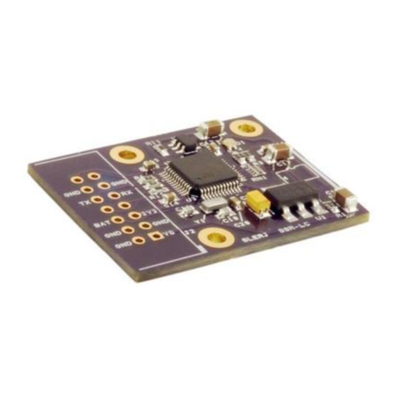
Figure 1. Top View (SSR-LC-TS shown) microSD Card Slot (push-push type connector) Figure 2. Bottom View (SSR-LC-TS shown) CAUTION: Like most electronic components, the SSR-LC can be damaged by electrostatic discharge. Observe typical precautions for handling electrostatic discharge sensitive devices. © 2019 Slerj, LLC... -
Page 6: Connecting The Ssr-Lc
PWM/digital input command pin (PDI, pin 13) is connected to ground and the shell is not active (pin 7 is allowed to float high). To access the SSR-LC interactive shell, tie pin 7 to ground. Default serial parameters are 115200 baud, 8 data bits, no parity, and 1 stop bit. While the shell is active (pin 7 is low), all received bytes goes to the shell and no data is recorded. - Page 7 SSR-LC User’s Manual Rev E, 2 September 2019 Default command source is -dig. Pull PDI down to record. Note that the device will not record while SH is pulled low for shell access. Figure 3. Typical connections using a 4.5 to 15 VDC supply...
- Page 8 Note that the SSR-LC serial parameters (baud, data bits, parity, stop bits) must match the device to be recorded. The internal 40kΩ pull up resistors of the SSR-LC input pins may not be sufficient to keep the pins high in electrically noisy environments. In those cases, it is recommended to use stronger pull-ups (e.g., 4.7 kΩ) sourced from the on-board 3.3V supply (3V3, pin 5).
-
Page 9: Using The Ssr-Lc
SH is high. The interactive shell is accessible through the serial interface when SH is low. On power up, the SSR-LC displays a boot loader announcement and device details. If SH is low, the shell prompt will be presented. A typical power-on sequence would produce output similar Slerj Boot Loader v1.0.0... -
Page 10: Functional Overview
Echo – (Boolean) Echoes received characters out through the transmitter. The single serial channel of the SSR-LC is attached to either the data recording subsystem or the user interface module based on the level of the SH input pin. - Page 11 The Soft Command parameter can be set through the user interface module (shell). File Type The SSR-LC supports three archive types: raw, tagged line , and time tagged archives. o When file type is raw, bytes are written to file just as they are received, and no timestamp information is attached to the data.
- Page 12 File Size The SSR-LC supports automatic file close and reopen when a size (or time) threshold is reached. Threshold values of 1 MB, 2 MB, 4 MB, 8 MB, 16 MB, 32 MB, 64 MB, 128 © 2019 Slerj, LLC...
-
Page 13: User Interface Module
Subsystem. Additionally, a status line is provided (ST) to indicate when the channel is recording. A bi-color (red and green) LED on the SSR-LC (Figure 1) provides status. The green segment flashes to indicate reception of serial data on the channel and indicates when the shell is active. -
Page 14: Interactive Shell
SSR-LC User’s Manual Rev E, 2 September 2019 4 Interactive Shell The interactive shell is designed to provide easy access to the SD card file system, device status, and configuration options. Entering ‘?’ or ‘help’ at the command prompt provides information about using the shell. -
Page 15: System Commands
SSR-LC User’s Manual Rev E, 2 September 2019 4.1 System Commands System commands provide access to general system functions including the real-time clock and operational status. Table 5. System Commands Command Aliases Description clear Clears the screen. date [yyyymmdd] Sets the current date to the year, month, and day specified. If no date is specified, this command returns the current date. -
Page 16: Device Configuration
(RAM) and can be saved to non-volatile memory for preservation across resets. On startup, if the contents of the non-volatile configuration memory are valid, the stored configuration is loaded and used by the SSR-LC. The shell provides access to device configuration through the following commands: Table 7. -
Page 17: Capturing The Shell
Option added in firmware 2.1.0 The SSR-LC does not support 7 data bits with no parity. A 7 bit data frame must have parity enabled. bool denotes a Boolean expression, and may be specified using { y | Y | t | T | true | yes | on } for affirmative and { n | N | f | F | false | no | off } for negative. - Page 18 The user must type those same characters in lower case to complete the capture process. If the challenge string is not answered in 5 seconds, the capture process is aborted and the SSR-LC starts normally. © 2019 Slerj, LLC...
-
Page 19: Time Tagged Archives
All multi-byte words in the archive are big endian. Note that a software utility, including source code, is provided at slerj.com for parsing time tagged archives into a variety of useful formats. See section 5.3 The STTP Utility for details. -
Page 20: Time Correlation Packet
The SLERJ Time Tagged Parser is a Windows command line utility (sttp.exe) provided with the SSR-LC to parse time tagged archives into various output types. Source code is provided under a non-restrictive (MIT) license so that it can be freely modified and incorporated into user applications. - Page 21 SSR-LC User’s Manual Rev E, 2 September 2019 Usage of the sttp utility is summarized by its help output: usage: sttp.exe [options] <infile> Version 1.5, Feb 21 2018 20:30:23 options: Include headers in tcp and dat files. -r <raw_file> Write raw stream data to raw_file -t <tcp_file>...
- Page 22 SSR-LC User’s Manual Rev E, 2 September 2019 Time Correlation Packet output example: RunTime(ms) Year Month Day Hour Minute Second 4196 2013 3 25 9 52 4.625 604196 2013 3 25 10 2 3.628 1204196 2013 3 25 10 12 2.486...
-
Page 23: Specifications
12 VDC Supply Idle Recording – LEDs Off Recording 1.65 BAT Supply Voltage Digital Input Characteristics (RX (SSR-LC-T), PDI, SH, Res) Low level input voltage 1.37 High level input voltage 1.85 Schmitt trigger hysteresis Weak pull-up equivalent resistor k Digital Output Characteristics (TX (SSR-LC-T), ST) Low level output voltage (±8mA) -
Page 24: Mechanical
SSR-LC User’s Manual Rev E, 2 September 2019 6.3 Mechanical Dimensions: 1.40 x 1.09 x 0.20 inches (36 x 28 x 5 mm) 5mm height is without header installed Hole Pattern: 0.750 x 0.850 inches (19.05 x 21.59 mm) Hole Diameter: 0.096 inches (2.44 mm) – Designed for No. 2 hardware. -
Page 25: Revision History
Changes 29 April 2014 draft release Removed field ‘c’ from Table 2 because the SSR-LC has only a single channel, so that 25 Sept. 2014 providing a channel number for file names is meaningless. Also, the File Path section of 3.2 Data Recording Subsystem was updated to use an example without the ‘c’...
Need help?
Do you have a question about the SSR-LC and is the answer not in the manual?
Questions and answers