Advertisement
Quick Links
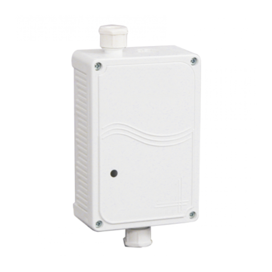
BSR-8020/WP/MAR
OPERATION VOLTAGE
QUIESCENT CONSUMPTION
ALARM CONSUMPTION
QUIESCENT CONSUMPTION WHEN USED AS A CONVENTIONAL DEVICE DRIVER
ALARM CONSUMPTION WHEN USED AS A CONVENTIONAL DEVICE DRIVER
EXTERNAL POWER SUPPLY
INSTALLATION
DEGREES OF COVER PROTECTION
PRODUCED IN ACCORDANCE WITH
OPERATION TEMPERATURE RANGE
RELATIVE HUMIDITY
CONSTRUCTIONAL MATERIAL
DIMENSIONS
WEIGHT
GUARANTEE
GENERAL
The input-output unit is used in ships. It is recognized and programmed by the BSR-2100 panel. This device is used to
connect to the loop non-addressable devices that have a free relay contact (such as fire alarm panels, flow switches and
conventional detectors). The input unit is fully monitored and can send to the panel, with a suitable connection, three states:
quiescent, fault, alarm. The output unit contains a fully programmable by the panel relay with a rating of (30V/1A).
The red LED that blinks periodically in the quiescent state is an indication of power and good operation. The LED lights and
remains lit when the specific input unit issues an alarm to the panel. The LED also remains lit if the sirens are deactivated
from the panel in order to show the precise point where the alarm originated from. The Led is turned OFF after a panel
reset. Each device must have an address, that is recognized by the panel. It is not allowed for two devices on the same
loop to have the same address. Page 4 contain the full table that shows the addresses and how they can be set with the
micro switches. Up to 127 units can connected to each panel.
INSTALLATION (Notice!!! The mounting accessories are included)
1. Unfasten the front cover screws and remove the cover.
2. Locate the mounting holes and use the supplied accessories to mount the unit on the required position.
3. Pass the cables through the cable glands and make the required connections.
4. Notice!! If an additional entry hole is required then remove the break-out plastic and install the supplied cable gland.
5. Set the address on the dip-switch (page 4 and 5).
6. Reinstall the front cover and fasten the screws that were removed in step 1.
Indicator LED
4
Page 1 from 9
Waterproof addressable input-output unit
Technical characteristics
Thank you for your trust in our products
Olympia Electronics - European manufacturer
1
1.3mA (with activated LED)
For internal use only
EN 54-18, IEC 60092-504, IEC 60533
2
3
5
3
2
21-28V
0.7mA
5.6mA
30mA
21-28V
IP65
o
-10 to 60 C
Up to 95%
Bayblend FR3010
155x80x43mm
170gr.
2 years
921802003_09_005
ON
OFF
Advertisement

Related Manuals for olympia electronics BSR-8020/WP/MAR

Summary of Contents for olympia electronics BSR-8020/WP/MAR
- Page 1 2 years GUARANTEE Thank you for your trust in our products Olympia Electronics - European manufacturer GENERAL The input-output unit is used in ships. It is recognized and programmed by the BSR-2100 panel. This device is used to connect to the loop non-addressable devices that have a free relay contact (such as fire alarm panels, flow switches and conventional detectors).
-
Page 2: Operation
OPERATION The device has 4 different operation modes: 1) Input/Output Unit In this function input and output units are independent. The input unit is used in order to connect non addressable devices, that have a free relay contact (such as conventional alarm panels, or flow switches), to the loop of the panel. The input unit is fully monitored and has the capability to send to the panel, with a suitable connection, three states: quiescent, fault, alarm. - Page 3 Input connection terminals. The input is fully monitored and has by default a (56kΩ) resistor. On the 24V IN terminal you can connect an external power supply if the function conventional detector driving unit with external power supply is selected. Relay connection terminals (NO, C, NC) Address select dip-switch (1-7)
- Page 4 Microswitch Microswitch Microswitch Microswitch Address Address Address Address setting setting setting setting 921802003_09_005 Page 4 from 9...
- Page 5 (short circuit), the output of the device does not operate and the message “ DISABLEMENT ” is shown on the panel. The dip-switch 8 of the BSR-8020/WP/MAR must be in the ON position. It can be used in a fire extinguishing system.
- Page 6 24V power supply from panel BS-685 BS-685 BS-686 BS-686 Loop 10kΩ Connecting gas detectors Connecting a BSR-8020/WP/MAR with detectors ΒS-685 or ΒS-686. The auxiliary relay is used to interrupt the power to the detectors after a reset. 921802003_09_005 Page 6 from 9...
- Page 7 Loop 10kΩ Connecting a BSR-8020/WP/MAR with conventional detectors. A 10kΩ terminal resistor must be connected on the last detector. The maximum number of detectors per unit is 10. An external LED BS-572 can be connected on one of the detectors. With the dip-switch 8 we can set if during an alarm the zones power will be interrupted or not.
- Page 8 4.7kΩ Connecting a BSR-8020/WP/MAR to conventional detectors. A 4.7kΩ resistor must be installed on the last detector. The maximum number of detectors per device is 40 conventional detectors of olympia electronics. According to EN 54 the maximum number of detectors per zone is 32 devices.
- Page 9 Olympia Electronics or if the buyer modifies the goods provided or has any repairs or re- setting done by a third party, unless Olympia Electronics has fully agreed to them in writing.
Need help?
Do you have a question about the BSR-8020/WP/MAR and is the answer not in the manual?
Questions and answers