Table of Contents

Subscribe to Our Youtube Channel
Related Manuals for Raveon RV-M9


Summary of Contents for Raveon RV-M9
- Page 1 RV-M9 Mils-Spec GPS Transponder UHF GPS Transponder/Modem Tech n ic a l Man ua l Version B February 2019 RF-M9 Raveon Technologies Corporation 2320 Cousteau Ct Vista CA 92081 www.raveon.com Company Confidential Raveon Technologies Corp.
-
Page 2: Table Of Contents
Table of Contents General Information about the RV-M9 ............4 1.1. Congratulations! ..........................4 1.2. NOTICE ............................4 1.3. Safety / Warning Information ......................4 1.4. Safety Training information: ............Error! Bookmark not defined. 1.5. FCC Compliance Information ......................5 Overview ....................... - Page 3 RGI Polled Remote Position ......................35 12.2. NMEA Type Messages ........................ 36 12.3. $GPTLL Target Lat-Lon ....................... 36 12.4. $GPGSV Satellites In View ......................37 12.5. $GPWPL Waypoint Location ...................... 37 12.6. $PRAVE Raveon Proprietary Message, Location-Status ............38 Company Confidential Raveon Technologies Corp.
-
Page 4: General Information About The Rv-M9
1.1. Congratulations! Congratulations on your purchase of a RV-M9 GPS tracking radio. Please take a few minutes to read this manual carefully. The information presented here will allow you to derive maximum performance from your radio modem. After reading it, keep the manual handy for quick reference, in case questions arise later on. -
Page 5: Fcc Compliance Information
OET-65C (01-01) when operated in accordance with the operation guidelines described in this manual. Proper operation of this radio device according to the instructions in this publication will result in user exposure substantially below the FCC recommended limits. Company Confidential Raveon Technologies Corp. -
Page 6: Overview
6-channel GPS receiver. It has ½ to 5 watts of RF power output, and operates as a GPS transponder for tracking, and a radio modem for sending and receiving data. As well as sending position and status, the RV-M9 also has a radio modem with integrated Ethernet 10/100 Base-T interface. -
Page 7: 10/100Base-T - Tcp/Ip Socket Connections
Any RV-M9 that is a TXRX may be either a PRIMARY or a SECONDARY. Primary transmitters use TDMA slot 1 to transmit their GPS location in, and Secondary transmitters use TDMA slot 2 to transmit their GPS locations in. The second parameter of the MODE command is either a P or S for Primary or Secondary. -
Page 8: Roles
Command Mode, whereas session authenticated with DATA credentials shall operate in Data Mode. When a given RV-M9 telnet session is in Data Mode, it will not accept user-commands. It will output over-the-air data or GPS information whenever the unit receives it. Arbitrary data may also be scheduled for transmission over-the-air by simply entering it via a telnet session operating in this mode. - Page 9 Do not attempt to login to the System Recovery IP address unless you want to erase all settings within the unit. After the unit has been running more than 30 seconds, the System Recovery IP address is disabled. Company Confidential Raveon Technologies Corp.
-
Page 10: Specifications
Temperature resolution and accuracy (enclosure temperature) ......... 2 degrees C/4 degrees C Number of digital inputs ...........................0 Velocity resolution and accuracy ..................1km / 1km per hour GPS connector ............................TNC Active GPS antenna voltage (RV-M9 output voltage on SMA) ........3.3V, 20mA maximum Company Confidential Raveon Technologies Corp. -
Page 11: Electrical Inputs And Outputs
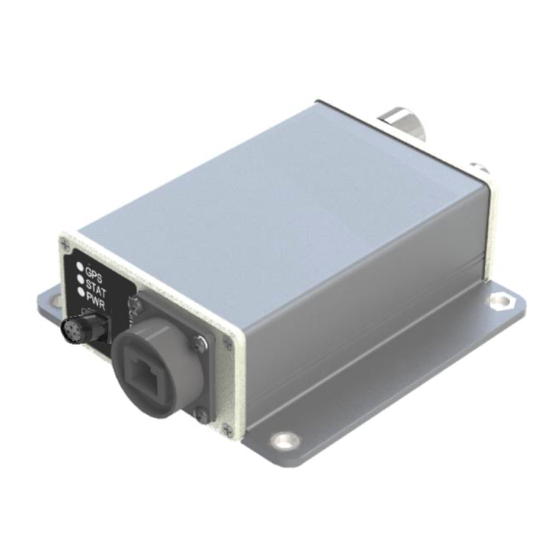
4. Electrical Inputs and Outputs The front panel of the RV-M9 modem has these features: 1. Power LED (red blink = on, green blink = telenet connected) 2. Status LED (Receive data = green, Transmit = red) 3. GPSLED (off = failed/no GPS, red = locking, green = locked) 4. -
Page 12: Setting A Parameter
If certain parameters within the RV-M9 transponder are modified in a manner that erroneously causes the modem to cease functioning or if the user cannot enter Command Mode via an ADMIN telnet session, there is a small push-button internal to the RV-M9 to Company Confidential... -
Page 13: Restoring Factory Defaults
This “CONFIG” button may be pressed at any time, and forces the RV-M9 into a known operational state. The CONFIG button is located inside the RV-M9. The default settings that the RV-M9 will revert to when the CONFIG button is pressed are: 1. -
Page 14: Modem Commands
60000mS RV-M9 is pressed, this parameter will be automatically set to 60000. Destination Address to call– Sets address of the modem to send data to. Note, in the RV-M9 this parameter is ATDT Range: 0-9999 0001 entered in decimal format. Each digit may be a 0,1,2,3,4,5,6,7,8, or 9. - Page 15 (Varies based Preamble length – The number of bytes to send over-the- ATR5 Range: 3 - 255 on data rate air in the pre-amble. and radio type. 7 typical) Company Confidential Raveon Technologies Corp.
- Page 16 Sleep Mode Operation Enable – When set to 1, the DTR input line controls the RV-M9’s low-power operation. When set to 0, the RV-M9 will not go into LPM, regardless ATSM of the state of the DTR pin. When set to 2, the modem is...
- Page 17 Set Prompt. Set/read the command-line text prompt. None SHOW Show/display an overview of the radio’s configuration. None ** indicates values that are calibrated in the factory and are unit-specific. If the “Radio Type” is changed, these will need to be re-calibrated. Company Confidential Raveon Technologies Corp.
-
Page 18: Gps Related Commands
Default is a capitol letter V. “0” for no prefix. Enable - Repeating. This simple command enables the repeater feature of the RV-M9 , and 0 off configures it for standard operation. The user may REPEAT alternately use the ATX and ATRX commands, but configure they are more complicated to use. - Page 19 Even if the unit is not moving, the GPS TXRATE 0 - 9999 periodically measures position and speed to determine if it has triggered a speed or position transmission. Set to TXRATE and IDLERATE both to 0 to totally disable position reporting. Company Confidential Raveon Technologies Corp.
-
Page 20: Ethernet Related Commands
“Dotted quad decimal” notation is also known as “dotted decimal” notation. Because changes to these settings may disable Ethernet access to the radio modem, requested changes to these settings must be confirmed by user action. Immediately following entry of each of these parameter change requests, the RV-M9 will respond with: Enter YES<CR>... -
Page 21: Factory - Default Settings
Factory – Default Settings 5.10. For the UHF RV-M9 model, the factory default settings are as shown in the command tables above and the list below: Radio channel 1frequency ..........464.500 MHz GPS Mode ..............14 (Polled with RGI command) Company Confidential Raveon Technologies Corp. -
Page 22: Setup And Initial Configuration
3. Connect a telnet client to port 23 of the RV-M9. The default IP address is 192.168.26.4 and the default network mask is: 255.255.255.0. Enter the DATA role credentials (default login: data, password: data). -
Page 23: Programming Channels And Frequencies
6.1. Programming Channels and Frequencies The RV-M9 modem has memory for up to 6 channels. In most applications, only one channel is needed. A channel is a pair of frequencies, one for transmit and one for receive. They may be different or they may be the same. You may program any valid frequency into any channel number. -
Page 24: Position Transmission
TDMA time slot. By default, each RV-M9 is assigned a time slot, based upon its ID. ID 1 is slot 1, ID 2 is slot 2…... -
Page 25: Device Addressing
It is up to the user to select and set this phrase. If the RV-M9 is not used in a system where security and privacy are a concern, then it is OK to leave the factory-set phrase. -
Page 26: Time Slots
1-9. Slot 0 is reserved. 7. Operation Once power is applied to the RV-M9, the internal GPS will begin to try to lock onto the GPS satellites. The PWR led on the front will begin to blink every two seconds. -
Page 27: Technical Information
For example, if the TXRATE is set to 120 (2 minutes), the RV-M9 will power the GPS off for most all of this time, only turning on the GPS long enough before it needs to transmit so that it can get a position fix. -
Page 28: Broadcast Transmissions
Destination Address of the transmission is logically “ANDed” with the Address Mask in the receiving modem. This is the Effective Destination Address. The receiving RV-M9 also ANDs its own Unit Address with its Address Mask. The result is the Effective Unit Address. -
Page 29: Tdma Overview
When a RV-M9 wants to report its position and status, it waits until its assigned time-slot, and then transmits its data. By default, TDMA time slot positions are assigned by unit-ID, so RV-M9 with ID 1 uses the first slot, and ID 2 uses the second slot, and so on. -
Page 30: Configuring Tdma Operation
All TDMA frames are synchronized automatically in all RV-M9 transponders to the top of the minute. Slot 0, frame 0 is at the top of each minute. 8.3. Configuring TDMA Operation Step 1. Determine your over-the-air baud rate. See section 11.3 for information on baud-rate selection. -
Page 31: Debug Related Commands
If it does, it answers with a response transmission, containing its ID and the signal strength of the reception. ATST Display statistics of how the modem is working. Display statistics of how the modem’s GPS is working. ATST 1 Company Confidential Raveon Technologies Corp. -
Page 32: Tune-Up And Alignment
2. Key the transmitter into a 50 ohm load using the ATTD 3 command. The unit will now transmit, and send a digital 0 continuously. This should be +2.0kHz in frequency for narrow-band radios (12.5kHz spaced channels) and +4.0kHz for wide-band (25kHz channels). Company Confidential Raveon Technologies Corp. -
Page 33: Tx Modulation Balance
The frequency response of the demodulated FM signal must be greater than 10Hz to 5kHz without any de-emphasis. 2. Transmit random data with the RV-M9, using the ATDT 1 command. This command will cause the RV-M9 to automatically key up, and send random data for one minute. -
Page 34: Rv-M9 Diagnostic Provisions
9.2. Reading the Diagnostic Information RV-M9 diagnostic information is read using AT commands, while the unit is in the Command Mode. Refer to the section “User Serial Port Commands” to learn how to put the RV-M9 modem into the Command Mode. -
Page 35: Rv-M9 Messages
10. RV-M9 Messages 10.1. RGI Polled Remote Position RGI,UTC,LAT,LAT DIR,LON LON DIR,ALTITUDE,SPEED,HEADING,STAT Field Usage Comments $ RGI Header for this message UTC time Ltitude North / south Longitude East West Altitude SPEED Speed I km/h HEAD Heading, 0 - 359 degrees... -
Page 36: Nmea Type Messages
GPS 3 mode of operation, it will output this message every time it receives a position report from another RV-M9 transponder. Within the TLL message, is the latitude, longitude, and Target ID”. In the Target ID field, the RV-M9 puts the ID of the RV-M9 that transmitted its position. -
Page 37: Gpgsv Satellites In View
NMEA checksum When the RV-M9 is set to GPS 4 mode of operation, it will output this message every time it receives a position report from another RV-M9 transponder. Within the WPL message, is the latitude, longitude, and “waypoint ID”. In the waypoint ID field, the RV-M9 puts the ID of the RV-M9 that transmitted its position. -
Page 38: Prave Raveon Proprietary Message, Location-Status
Transponder with ID 0003. $GPWPL,4917.16,N,12310.64,W,Car3*65 And on a GPS display connected to the RV-M9, the waypoint will show up at the correct lat/lon with the waypoint name “Car3”. In most all GPS receivers, this waypoint will also be added to its internal database of waypoints. - Page 39 The number of satellites in view Altitude The altitude in meters. Null field if no GPS lock. Temperature The internal temperature of the RV-M9 in degrees C. Typically this is 5-20 degrees above ambient. Voltage Input voltage to the device that sent this position.
- Page 40 $GPVTG,0,T,,,0.00,N,0.00,K,*1F $GPGLL,3308.7273,N,11713.7880,W,155823,A,*17 $GPVTG,28,T,,,1.08,N,2.00,K,*2E $GPGLL,3308.7226,N,11713.7896,W,155833,A,*11 $GPVTG,140,T,,,1.62,N,3.00,K,*1C $GPGLL,3308.7140,N,11713.7860,W,155843,A,*1C $GPVTG,260,T,,,1.62,N,3.00,K,*1D $GPGLL,3308.7134,N,11713.7998,W,155853,A,*18 $GPVTG,266,T,,,3.24,N,6.00,K,*1E $GPGLL,3308.7145,N,11713.8037,W,155903,A,*19 $GPVTG,74,T,,,3.78,N,7.00,K,*27 $GPGLL,3308.7182,N,11713.7927,W,155913,A,*14 $GPVTG,56,T,,,2.70,N,5.00,K,*2C $GPGLL,3308.7224,N,11713.7891,W,155923,A,*14 $GPVTG,56,T,,,1.08,N,2.00,K,*27 $GPGLL,3308.7233,N,11713.7899,W,155933,A,*1B $GPVTG,0,T,,,0.00,N,0.00,K,*1F $GPGLL,3308.7219,N,11713.7902,W,155943,A,*17 $GPVTG,0,T,,,0.00,N,0.00,K,*1F Company Confidential Raveon Technologies Corp.
Need help?
Do you have a question about the RV-M9 and is the answer not in the manual?
Questions and answers