Table of Contents

Subscribe to Our Youtube Channel
Related Manuals for Raveon RV-M6S


Summary of Contents for Raveon RV-M6S
- Page 1 RV-M6S / RV-M6G Da ta Radio Modem Module Optional GPS Tracking Te c hn ical Ma nu al Version A8 March 2021 Raveon Technologies Corporation 2320 Cousteau Court Vista, CA 92081 www.raveon.com Company Confidential Raveon Technologies Corp.
-
Page 2: Table Of Contents
Broadcast Transmissions ........................31 The Address Mask..........................31 Addressing Examples: .......................... 32 8.5. Store-and-Forward Repeating ...................... 33 Automatic Repeater Configuration ....................... 33 Manual Configuration of the Repeat Feature ..................33 Debug Related Commands ................. 52 Company Confidential Raveon Technologies Corp. - Page 3 Symptom: Receive light blinks, but no data is received ............... 58 Symptom: Long delay before transmitting ..........Error! Bookmark not defined. Symptom: Cannot enter Command Mode ................... 59 Symptom: Modem appears dead......................59 Symptom: Repeater will not repeat..................... 59 Mechanical....................60 Company Confidential Raveon Technologies Corp.
-
Page 4: General Information About The Rv-M6
1.2. NOTICE There are no user-serviceable points inside this transceiver. All service work must be referred to your Authorized Service Center or Raveon Technologies Service Department. NOTE: This equipment has been tested and found to comply with the limits for a Class A digital device, pursuant to part 15 of the FCC Rules. - Page 5 It is not intended for portable applications. The RV-M6S-UC (UHF version) safety information: The maximum permissible exposure to the antenna is: The minimum separation distance is 30cm.
- Page 6 The product is only to be operated at frequencies allocated by local authorities, and without exceeding the given maximum allowed output power ratings. Raveon and its distributors are not responsible, if any products manufactured by it are used in unlawful ways.
-
Page 7: Overview
2. Overview The M6 RF radio modem module is capable of high-speed narrow-band data communications and is compatible with Raveon’s M7 and M6 series Radio Modems. Its powerful microprocessor enables it to perform as both a data radio modem and a paging receiver. - Page 8 The STAT2 pin is used to trigger the Boot Loader. See application note AN186 for details on how to boat load new firmware into the M6. Company Confidential Raveon Technologies Corp.
-
Page 9: Specifications
POCSAG 512 sensitivity (<99% PER) ..........< -120dBm RF No-tune bandwidth ..............20MHz Channel spacing ................. 12.5kHz Adjacent Channel Selectivity 12.5kHz ..........-50dB Alternate Channel Selectivity ............-65dB Blocking and spurious rejection ............-75dB RX intermodulation rejection ............-70dB Company Confidential Raveon Technologies Corp. -
Page 10: Interface Specifications
3.4. Interface Specifications Connector Type .......... 20-pin 2mm header DC Input ............. 6-14V (Clean or regulated, contact Raveon for other voltages) DC power draw, RX mode ....... < 600mW DC power draw, TX mode, 2W ....< 6W DC current draw, standby mode ..... < 150uA IO Voltage Levels ........ -
Page 11: Electrical Inputs And Outputs
STAT1 and STAT2. Unused. Do not connect to anything. STAT2 Output to drive external dual-color LED. Do not connect the LED to ground or DC voltage. System Ground to M6 Unused. Do not connect to anything. Company Confidential Raveon Technologies Corp. -
Page 12: Heatsinking
The Red LED will blink when the modem transmits, and the green LED will blink on receive of data. It will also blink orange when decoding a POCSAG message. Company Confidential Raveon Technologies Corp. - Page 13 4.6. I/O Options (RS232, 485, USB, 422, Digital I/O …) The RV-M6 OEM radio module is designed to be integrated into other products. If there is a need for an enclosure and an I/O connector, contact Raveon for their Tech Series M22 enclosure with a myriad of I/O options.
-
Page 14: User Serial Port Commands
2. Input three (3) plus characters (“+++”) within ½ of a second. 3. No characters sent for ½ a second. When the M6 modem first enters the Command Mode, it sends the phrase “Raveon” followed by the model number Raveon M6S (transceiver version) out of its serial port, and then an “OK”... -
Page 15: Reading A Parameter
1. Serial port 9600 baud, 8 data bits 1 stop, no parity 2. ATCT setting set to 60000 (60 second time-out) 3. Serial port on the front of the unit in RS232 mode, 9600bps, N/8/1. Company Confidential Raveon Technologies Corp. -
Page 16: Exiting The Command Mode
3. Time Out. After a pre-set amount of time (60 seconds is the factory default time), the modem will automatically exit the Command Mode, and continue normal operation. Changes will not automatically be saved. This time-out duration may be set with the ATCT command. Company Confidential Raveon Technologies Corp. -
Page 17: Command Mode Commands
Enter in Hz or MHz. Same as Range: See product data ATFX issuing an ATFR and an ATFT command. The frequency will sheet. automatically be saved in non-volatile memory (flash) for this current channel number. M7 GX Technical Manual Raveon Technologies Corp. - Page 18 3 = 1010… at ¼ baud rate transmitting data. The type of data sent is set in the parameter. Entering a <CR> will terminate the transmission. 4 = TX all 0s 5 = TX all 1s M7 GX Technical Manual Raveon Technologies Corp.
-
Page 19: Data Modem Mode Related Commands
Destination Address to call– Sets address of the modem to ATDT send data to. Note, this parameter is entered in HEX format. Range: 0-FFFF 1234 Each digit may be a 0,1,2,3,4,5,6,7,8,9,A,B,C,D,E,or an F. M7 GX Technical Manual Raveon Technologies Corp. - Page 20 Preamble Detect. Returns 1 if the device is detecting a preamble PRDT pattern. Returns 0 if it does not. M7 GX Technical Manual Raveon Technologies Corp.
-
Page 21: Paging Receiver Related Commands
GPS receiver that will be sent out the serial GGA) port. The parameter is the decimal integer value of the mask. Set/Read NMEA message rate. Set/read the NMEARATE 1-99 number f seconds between NMEA messages from M7 GX Technical Manual Raveon Technologies Corp. - Page 22 SLOTQTY 1-9999 other than 1. For example, if set to 3, and the ID of the unit is 0008, the unit will be allowed to transmit in slots 8, 9, and 10. M7 GX Technical Manual Raveon Technologies Corp.
- Page 23 Command Command Description Parameters Default CNTTM NN XX Set counter reset time Interval. NN is the CNTTM 0-FF register number to configure, XXXX is decimal format value to set the NN register to. M7 GX Technical Manual Raveon Technologies Corp.
-
Page 24: Factory Default Settings
After the time expires, the bits that was st in XX is cleared to 0. See Raveon’s Application Note AN161 for details on how the MIMIC mode as SCADA features work with the M6 radio modem, and now better the MIMIC and SDACA features can do when the M6 is within the Tech Series enclosure with the GPIO interface. - Page 25 Over-the-air data modem baud rate: ....4800 baud, 2-level Serial port ............9600baud, N/8/1 Hardware flow control ........Off ID (ATMY) ............1234 Address Mask (ATMK) ........FFFF Frequencies Ch 1 ....462.2125 MHz M7 GX Technical Manual Raveon Technologies Corp.
-
Page 26: Using The M6 - Packet Data Mode
Packet Mode offers the user, most user applications will seamlessly work using the M6 in its Packet Mode. Repeatable and Routable. M6 packets are structured so that they may be repeated using a store-and-forward repeater, and/or routed using specialized hardware. M7 GX Technical Manual Raveon Technologies Corp. -
Page 27: Setup
3. Connect a computer terminal, or PC computer running HyperTerminal or Raveon’s Radio Manager, to the 9-pin I/O connector. The factory default serial ports settings are 9600 bps, 8 data bits, 1 stop, and no parity. -
Page 28: Programming Channels And Frequencies
2. Program the frequency for this channel x, using the ATFT, ATFR, or ATFX command. Note that the frequency my be entered in MHz as long as you use a decimal point. For Example, enter ATFX 450.1 to set the channel frequency M7 GX Technical Manual Raveon Technologies Corp. -
Page 29: Data Transmission
Busy-Channel Lock Out If your system operation require the M6 modem to monitor-before-transmit, of if you do not want the M6 to transmit on a channel that is busy, you can enable “Busy- M7 GX Technical Manual Raveon Technologies Corp. -
Page 30: Addressing (Packetized Mode Only)
4 bit data in the following way: Hexadecimal Table Hex # Binary Hex # Binary Hex # Binary Hex # Binary 0000 0100 1000 1100 0001 0101 1001 1101 0010 0110 1010 1110 0011 0111 1011 1111 M7 GX Technical Manual Raveon Technologies Corp. -
Page 31: Setting A System-Wide Address
The receiving M6 also ANDs its own Unit Address with its Address Mask. The result is the Effective Unit Address. The Effective Unit Address is compared to the Effective Destination Address, and if the two are identical, the data will be received. M7 GX Technical Manual Raveon Technologies Corp. -
Page 32: Addressing Examples
FFFF requires that all digits in the address match. . Example 3 (able to receive a data from a group, 1230 – 123F) Sending to Destination Address = 1236 Receiving M6 Unit Address = 1234 Receiving M6 Address Mask = FFF0 M7 GX Technical Manual Raveon Technologies Corp. -
Page 33: Store-And-Forward Repeating
Data is transmitted over-the-air in bursts called packets, and each packet has the Unit ID of the M6 that sent the data and the Destination ID of the unit that the data is intended for. M7 GX Technical Manual Raveon Technologies Corp. - Page 34 C, and is configured to repeat all messages to/from The following table illustrates one possible way the M6 could be programmed to accomplish this type of system. M7 GX Technical Manual Raveon Technologies Corp.
- Page 35 B. To view the Repeater Table, use the ATX command, with no parameter. To view a single entry in the table, use the ATXn, where n=1, 2, 3, or 4. M7 GX Technical Manual Raveon Technologies Corp.
- Page 36 0. For example, to disable entry 1, use the ATX1 0 0 0 0 command. There can be an issue with regard to store-and-forward repeating and busy channels, particularly on polled systems. Raveon’s M6 wireless modem has a number of provisions in it to make store-and-forward repeating work smoothly.
- Page 37 3. Connect a computer terminal, or PC computer running HyperTerminal, to the serial I/O connector. The serial I/O connector is 3.3V digital logic, so you may need a digital-RS232 voltage converter. Raveon’s Tech Series enclosures have these built, so you may plug the RV-M6G into the “S” interface of a Tech Series to do the RS232 conversion.
- Page 38 ATMY The individual ID of this unit. Default is 0001. Number all of your M6G transponders with a different MYID. Raveon recommends sequentially numbering them, starting at number 1. ATDT The address of the unit this modem will talk to. Default is 0001.
- Page 39 M6G in GPS mode 2 is shown below: -GX GPS mode RavTrack PC Serial Protocol : Raveon $PRAVE Serial port baud rate: 38400 N 1 Position TX Interval : 60seconds (will TX when still.) Proximity Alert...
- Page 40 GPS info GPVTG Notes: *1. –LX units typically do not have a GPS receiver in them. They receive position reports over the air from other units, but do not transmit position or status. M7 GX Technical Manual Raveon Technologies Corp.
- Page 41 The logic inside of the M6G shown is tested at a user- programmable rate, called the TXRATE. The TXRATE is the time interval between M6G position/status radio transmissions. Set to TXRATE and IDLERATE both to 0 to totally disable position reporting. Raveon Technologies Corp.
- Page 42 GPS Position Transmission Trigger Diagram Raveon Technologies Corp.
- Page 43 RV-M6 GX: RS-232 Pin Function 4 - DTR Input 0 7 - RTS Input 1 3 - TXD Input 2 5 - Ground There are 3 commands that must be configured to use the digital inputs: Raveon Technologies Corp.
- Page 44 The M6 will report the bit as a 1 if it changes state, or 0 if it did not change state. For example, to configure the unit to transmit position when bit 0 changes state, issue these commands: Raveon Technologies Corp.
- Page 45 Serial port transmit data is disbled because GPS mode 4 is normally used to connect the a hand-held or mobile GPS display to the M6G. The M6G will send $GPWPL messages to the GPS to display the location of Raveon Technologies Corp.
- Page 46 Output 0 disable the device from outputting any message when a position report is received. $PRAVE Raveon Position & Satus. Output 1 This message is sent out of the M6G when it is operating in the GPS 2 mode. This message is used by third-party and PC applications for tracking location and status information.
- Page 47 OK to leave the factory-set code. If it is important that the M6G transmissions and system be secure, Raveon suggest you program the KEY to be a random sequence of letters and numbers at least 8 digits long.
- Page 48 4 bit data in the following way: Hexadecimal Table Hex # Binary Hex # Binary Hex # Binary Hex # Binary 0000 0100 1000 1100 0001 0101 1001 1101 0010 0110 1010 1110 0011 0111 1011 1111 Raveon Technologies Corp.
- Page 49 Effective Unit Address. The Effective Unit Address is compared to the Effective Destination Address, and if the two are identical, the data will be received. Note: Logically 1 = 1, 0 = 0, 0 = 0, 1 = 0 Raveon Technologies Corp.
- Page 50 FFFF requires that all digits in the address match. . Example 3 (able to receive a data from a group, 1230 – 123F) Sending to Destination Address = 1236 Receiving M6G Unit Address = 1234 Receiving M6G Address Mask = FFF0 Raveon Technologies Corp.
- Page 51 Following is a list of the NMEA messages that are available (as of revision C2 of the Firmware). NMEA Bit Number Bit Mask (zero based) (hex format / decimal) Message 0×001 / 1 0×002 / 2 0×100 / 256 !AIVDM 0x200 / 512 Raveon Technologies Corp.
-
Page 52: Debug Related Commands
Ping another modem over the air. Transmits a request to xxxx to see if xxxx can hear the sending station. If it does, it answers with a response transmission, containing its ID and the signal strength of the reception. . STAT Display statistics of how the modem is working. Raveon Technologies Corp. -
Page 53: M6 Diagnostic Provisions
STAT 3 Date and time firmware was compiled. Run Time – Returns the amount of time that the modem has been Run time display STAT 4 powered up and running. screen STAT 9 Reset all statistics counters Raveon Technologies Corp. -
Page 54: Tune-Up And Alignment
All RF modems in the 2 = 2400 7 = 5142 2L network must use the same over-the-air baud rate. 3 = 4800 8 = 9600 4L 4 = 8000 4L 9 = 2000 2L Raveon Technologies Corp. -
Page 55: Center Frequency
RF, using an internal signal called RSSI (Receive Signal Strength Indication). The RSSI signal is an analog signal representing the strength of the RF carrier. It is compared with a pre-set value, and if it is above Raveon Technologies Corp. - Page 56 Output Data Framing takes place, it will go high (about 3V). Mode 5 - MIMIC Out 1 When a MIMIC over the air data is received, and the CD pin is set to ATR1 5 mode, then the CD pin will output bit 1 state. . Raveon Technologies Corp.
- Page 57 RF power for the board. This may vary by model number. See the data sheet for maximum RF power levels for various models. For a 2W RV-M6S radio modem, typical RF power levels are shown below. When setting the RF power below 100%, connect the M6 to a calibrated what meter and measure the power and adjust ATPO to set it to the desired power level.
-
Page 58: Troubleshooting
(ATSM 1), then the M6 will turn off when the DTR line is off, or the program connected to the serial port is closed, or the RS-232 connector is un plugged. Symptom: Receive light blinks, but no data is received Solution Raveon Technologies Corp. -
Page 59: Symptom: Cannot Enter Command Mode
If other units in the system have the same ID as the repeater, the repeater will not repeat them because it thinks the it originated the transmission. Set the MTID of the repeater to a unique ID number. Raveon Technologies Corp. -
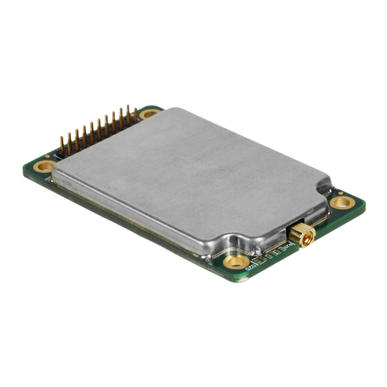
Page 60: Mechanical
13. Mechanical A drawing is shown below. Raveon Technologies Corp. - Page 61 Limited One Year Warranty If within 12 months from date of purchase, this Product fails conforms to Raveon Technologies Corporation’s (the Company) published specifications for the model purchased due to a defect in material or workmanship, Raveon Technologies Corporation will repair or replace it, at Raveon’s sole discretion.
- Page 62 Warranty service is available by mailing postage prepaid to: Raveon Technologies Corporation 2320 Cousteau Court Vista, CA 92081 - USA To obtain warranty service, include a copy of the original sales receipt or invoice showing the date, location, and price of purchase. Include a written description of the problem with the product, a phone number and name of person who may be contacted regarding the problem, and the address to where the product should be returned.
Need help?
Do you have a question about the RV-M6S and is the answer not in the manual?
Questions and answers