Table of Contents
Advertisement
Quick Links
10/100/1000M
Industrial Switching HUB
NZ2EHG-T8
User's Manual
Powered by CONTEC
This product was jointly developed and manufactured by Mitsubishi and
CONTEC.
Note that some of the warranty on this product differs from that on other
products (MELSEC-Q or MELSEC-L series).
(Refer to "Terms of Warranty".)
© 2010 MITSUBISHI ELECTRIC CORPORATION
MODEL
MODEL
CODE
IB(NA)-0800460-C(1007)MEE
NZ2EHG-T8-U
13J246
Advertisement
Table of Contents

Related Manuals for Mitsubishi NZ2EHG-T8

Summary of Contents for Mitsubishi NZ2EHG-T8
- Page 1 Industrial Switching HUB NZ2EHG-T8 User’s Manual Powered by CONTEC This product was jointly developed and manufactured by Mitsubishi and CONTEC. Note that some of the warranty on this product differs from that on other products (MELSEC-Q or MELSEC-L series). (Refer to "Terms of Warranty”.)
- Page 2 Precautions regarding Warranty and Specifications This product was jointly developed and manufactured by Mitsubishi and CONTEC. Note that there are some precautions regarding warranty and specifications of the product. <Warranty> The gratis warranty term of the product shall be for one (1) year after the date of delivery or for eighteen (18) months after manufacturing, whichever is less.
- Page 3 Safety Precautions Review the following definitions and precautions to use the product safely. Safety Information This document provides safety information using the following symbols to prevent accidents resulting in injury or death and the destruction of equipment and resources. Review the meanings of these labels to operate the equipment safely.
- Page 4 If you move or transfer the product, make sure to provide this manual with the product. Regardless of the foregoing statements, Mitsubishi is not liable for any damages whatsoever (including damages for loss of business profits) arising out of the use or inability to use this Mitsubishi product or the information contained herein.
- Page 5 CONDITIONS OF USE FOR THE PRODUCT Mitsubishi programmable controller ("the PRODUCT") shall be used in conditions; i) where any problem, fault or failure occurring in the PRODUCT, if any, shall not lead to any major or serious accident; and ii) where the backup and fail-safe function are systematically or automatically provided outside of the PRODUCT for the case of any problem, fault or failure occurring in the PRODUCT.
-
Page 6: Packing List
Packing List Thank you for purchasing this Mitsubishi product. The product package contains the items listed below. Check the contents of the product package. If you discover any damaged or missing items, contact the distributor. Contents Name Pcs. Industrial switching HUB unit (NZ2EHG-T8) User’s Manual... -
Page 7: Table Of Contents
Table of Contents Packing List ............................5 1. Before Using the Product About the Unit ............................. 7 Features ............................7 Environment ..........................8 Inspection ............................. 8 Storage............................8 Disposal ............................8 2. Part Names and Settings Part Names and Functions ........................9 3. -
Page 8: Before Using The Product
The automatic power adjusting function can reduce the power consumption by up to 80%. *1 With fan less configuration, NZ2EHG-T8 is suitable for places where silence is required. In addition, the adoption of metal casing with great radiation performance enables the unit to be used in ambient temperatures of 0 to 50°C. -
Page 9: Environment
1. Before Using the Product Environment Use this product in the following environment. If used under environmental conditions exceeding these ranges, the board may overheat, malfunction, or cause a failure. Operating temperature 0 to 50°C Operating humidity 10 to 90%RH (No condensation) Corrosive gases None Floating dust particles... -
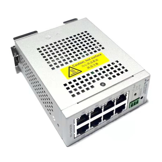
Page 10: Part Names And Settings
2. Part Names and Settings 2. Part Names and Settings Part Names and Functions Figure 2.1. Part names Table 2.1. LED indicators Name Status Color Display POWER LED POWER Green OFF : Power off ON : Power on LED:A 10Mbps Yellow OFF : No LINK 100Mbps... - Page 11 2. Part Names and Settings Table 2.3. 10BASE-T/100BASE-TX/1000BASE-T port Name Function 10BASE-T/ Ports 1 to 8 100BASE-TX/ Use these ports to connect personal computers, additional HUB units, bridges, or other 1000BASE-T port devices. Communication rate (10/100/1000Mbps) and communication method (half/full duplex) can be automatically recognized.
-
Page 12: Setup Of Hardware
3. Setup of Hardware 3. Setup of Hardware Mounting/Removing a Unit on/from a DIN Rail Mounting Procedure (1) Hook the upper clips of a DIN rail mounting bracket to the upper groove of a DIN rail, and then push the lower part of the unit to the DIN rail. Figure 3.1. -
Page 13: Removing Procedure
3. Setup of Hardware Removing Procedure A phillips-head screwdriver or a flathead screwdriver is required to remove a unit from a DIN rail. CAUTI ON Disconnect LAN cables and power cables connected to the unit before removing from the DIN rail. For a Phillips-head screwdriver (1) Insert a phillips-head screwdriver (diameter: 6 to 7mm) into the latch metal fitting on the lower part of the unit. - Page 14 3. Setup of Hardware (3) By lifting the unit, you can easily remove it from the DIN rail. Figure 3.5. Removing a unit from a DIN rail with a phillips-head screwdriver < 3 / 3 > For a flathead screwdriver (1) Insert a flathead screwdriver (tooth width 5.5 to 7mm) into the latch metal fitting on the lower part of the unit, and push the tip of the screwdriver down vertically.
-
Page 15: Attaching Mounting Brackets
3. Setup of Hardware (3) By lifting the unit, you can easily remove it from the DIN rail. Figure 3.8. Removing a unit from a DIN rail with a flathead screwdriver < 3 / 3 > Attaching mounting brackets Attachment Remove the four screws and separate the DIN rail mounting bracket from the unit. -
Page 16: Attaching A Retention Bracket
3. Setup of Hardware Mounting brackets Attach mounting brackets to the unit using bracket screws. Figure 3.10. Attaching mounting brackets Attaching a retention bracket Attachment (1) Plug in the power terminal connector to the power connector and attach the retention bracket using a bracket screw. -
Page 17: Installation Conditions
3. Setup of Hardware Installation Conditions CAUTI ON When used in applications with high environmental temperatures, even if the unit is operated within the temperature range specification, make sure that heat generated by the unit has an adequate dissipation path. Installation Orientation When a DIN rail mounting bracket is used Avoid installation in an unsuitable installation orientation as insufficient heat dissipation may occur. - Page 18 3. Setup of Hardware When mounting brackets are used Installation in any orientation is possible. (Top) Suitable installation orientations (Bottom) (Top) (Bottom) Figure 3.13. Installation orientations (with mounting brackets)
-
Page 19: Spacing Between Unit And Surrounding Objects
3. Setup of Hardware Spacing between Unit and Surrounding Objects CAUTI ON Do not install the unit in a sealed housing. When installed using a DIN rail mounting bracket Ensure the distance between the unit and any surrounding objects as follows: Above and below the unit: 50mm or more Sides of the unit: 50mm or more (At least 5.8mm on the rating plate side). - Page 20 3. Setup of Hardware When installed using mounting brackets Ensure the distance between the unit and any surrounding objects as follows: Above and below the unit: 50mm or more Under the rating plate side of the unit: 5.8mm or more On each side of the unit: 50mm or more Figure 3.15.
-
Page 21: Connecting To A Network
4. Connecting to a Network 4. Connecting to a Network Network Cables Cables meeting the following specifications should be used: 10BASE-T : Category 3 or higher UTP, STP cable 100m or less 100BASE-TX : Category 5 or higher UPT, STP cable 100m or less 1000BASE-T : Category 5e or higher UTP, STP cable 100m or less There are two types for UTP and STP cables: a straight-through cable and a crossover cable. -
Page 22: Connection Restrictions For 100Base-Tx Repeater Hubs
4. Connecting to a Network Connection Restrictions for 100BASE-TX Repeater HUBs Using Class I 100BASE-TX repeater HUBs, cascade connections are not possible. Up to two stages of cascade connections are possible with Class II 100BASE-TX repeater HUBs. In addition, the maximum total length of cables (1) (2) (3) is 205m or less. -
Page 23: System Reference
5. System Reference 5. System Reference Specifications Table 5.1. Specifications Item Specifications Ethernet standards IEEE802.3/IEEE802.3u /IEEE802.3ab –compliant Data communication rate 10/100/1000Mbps (auto-recognition) Access method CSMA/CD Communication method All ports: Full/Half duplex (auto-recognition) Topology Star topology Flow control Full Duplex : IEEE802.3x compliant flow control Half Duplex :Back pressure Number of effective ports Switching method... - Page 24 5. System Reference Table 5.2. Installation environment requirements Item Specification Operating ambient temperature 0 to 50°C Storage ambient temperature -10 to 60°C Ambient humidity 10 to 90%RH (No condensation) Floating dust particles Tolerant of small amounts (non excessive) Corrosive gases None Line-noise AC line/2kV, Signal line/1kV (JIS C61000-4-4 Level 3, IEC61000-4-4 Level 3)
-
Page 25: External Dimensions
5. System Reference External Dimensions Figure 5.1. External dimensions with a DIN rail mounting bracket (standard) Figure 5.2. External dimensions with mounting brackets... -
Page 26: Emc Directive
This product is compliant to with EN55022, EN55024, and EN61000-6-2. (1) Authorized representative in EU member states The authorized representative in EU member states will be: Company name : Mitsubishi Electric Europe BV Address : Gothaer strasse 8, 40880 Ratingen, Germany... - Page 27 MEMO...
- Page 28 6. Failure caused by reasons unpredictable by scientific technology standards at time of shipment from Mitsubishi. 7. Any other failure found not to be the responsibility of Mitsubishi or that admitted not to be so by the user.
- Page 29 2. Onerous repair term after discontinuation of production (1) Mitsubishi shall accept onerous product repairs for six (6) years after production of the product is discontinued. Discontinuation of production shall be notified with Mitsubishi Technical Bulletins, etc. (2) Product supply (including repair parts) is not available after production is discontinued.
- Page 30 Revisions *The manual number is given on the bottom right of the cover. Print Date *Manual Number Revision January 2010 IB(NA)-0800460-A First edition February 2010 IB(NA)-0800460-B Partially revised Precautions regarding Warranty and Specifications, Safety Precautions, Chapter 2, 3 and 5 July 2010 IB(NA)-0800460-C Partially revised...