
Subscribe to Our Youtube Channel
Summary of Contents for thermosolar SR14
- Page 1 Temperature Difference Controller SR 14 Installation and operating instructions applies to SR14 versions V1, V2, V3, V4 SR 14 Read carefully before installation, commissioning and operation...
-
Page 2: Table Of Contents
Content 7. - Special functions 7.1. - Program selections A.1. - EC declaration of conformity 7.2. - Signal V1 A.2. - General instructions 7.2.1. - Type of signal A.3. - Explanation of symbols 7.2.2. - Profi le A.4. - Changes to the unit 7.2.3. - Page 3 This manual applies to the following hardware versions: SR14 Version 1 3 temperature sensor inputs 1 relay output 230 AC (on/off) SR14 Version 2 3 temperature sensor inputs 1 electronic relay output 230 AC (for speed control of standard pumps)
-
Page 4: Ec Declaration Of Conformity
Safety instructions A.1. - EC declaration of conformity By affi xing the CE mark to the unit the manufacturer declares that the SR14 conforms to the following relevant safety regulations: EC low voltage directive 2006/95/EC EC electromagnetic compatibility directive 2004/108/EC Conformity has been verifi... -
Page 5: Changes To The Unit
Safety instructions A.4. - Changes to the unit Changes to the unit can compromise the safety and function of the unit or the entire system. Danger - Changes, additions to or conversion of the unit are not permitted without the written permission from the manufacturer - It is likewise not permitted to install additional components that have not been tested together with the unit - If it becomes clear that safe operation of the unit is no longer possible,... -
Page 6: Specifi Cations
Description of controller B.1. - Specifi cations Mains voltage 230 AC +/- 10% Mains frequency 50 - 60Hz Power consumption ~ 1.5VA Internal fuse 2A slow blow 250V Protection category IP40 Protection class Overvoltage Category Degree of Pollution Category Vers.1 Vers.2 Vers.3 Vers.4... -
Page 7: About The Controller
The SR14 can be used as a temperature difference controller for the various system variants illustrated and explained under B.5. Important characteristics of the SR14 :... -
Page 8: Scope Of Supply
- 4 strain relief clips with 8 screws, replacement fuse 2A slow blow - 1 connection clamp for PE terminal block. - Installation and operating instructions SR14 Optionally contained depending on design/order: - 2-3 Pt1000 temperature sensors and immersion sleeves... -
Page 9: Hydraulic Variants
Description of controller B.7. - Hydraulic variants The following illustrations should be viewed only as schematic dia- grams showing the respective hydraulic systems, and do not claim to be complete. The controller does not replace safety devices under any circumstances. Depending on the specifi c application, additional system Caution components and safety components may be mandatory, such as check valves, non-return valves, safety temperature limiters, scalding protec-... -
Page 10: Wall Installation
Installation Wall installation Install the controller only in dry areas and under the ambient conditions de- scribed under 2.1 “Specifi cations”. Carry out the following steps: Caution 1.Unscrew cover screw completely C.1.1 2.Carefully pull upper part of housing from lower part. 3.Set upper part of housing aside, being sure not to touch the electronics when doing so. -
Page 11: Electrical Connection
Installation Electrical connection Before working on the unit, switch off the power supply and secure it against being switched on again! Check for the absence of power! Electrical connections may only be made by a specialist and in Danger compliance with the applicable regulations. Do not use the controller if the housing shows visible damage. - Page 12 Installation 5. Connect the female connector block ‘s screw driver C.2.1.c clamp connections as described in the terminal connection plans. When using stranded cables, use a small screw driv- er and push the orange buttons while inserting (see fi g. C.2.1.c). When using solid cable or end splice, just push the cables in (see fi...
-
Page 13: Installing The Temperature Sensors
Installation To remove the female connector block C.2.1.f from the header, carefully bend the latch on the header. Caution: The latch breaks easily. Installing the temperature sensors The controller operates with Pt1000 temperature sensors which are accurate to the degree, thus ensuring optimal control of system functions. Position the sensor precisely in the area to be measured! Only use immersion, pipe-mounted or fl... -
Page 14: D Terminal Connection Diagrams
Sensor 2 Storage S3 (2x) Sensor 3 (optional) The polarity of the sensors S1-S3 is freely selectable. V1 / - 0-10V or PWM +/- ( SR14 Version 3+4) Mains voltages 230 VAC 50-60Hz Terminal: Connection for: Mains phase conductor L... - Page 15 Sensor 2 Storage S3 (2x) Sensor 3 (optional) The polarity of the sensors S1-S3 is freely selectable. V1 / - 0-10V or PWM +/- ( SR14 Version 3+4) Mains voltages 230 VAC 50-60Hz Terminal: Connection for: Mains phase conductor L...
- Page 16 Sensor 2 backward fl ow S3 (2x) Sensor 3 (optional) The polarity of the sensors S1-S3 is freely selectable. V1 / - 0-10V or PWM +/- ( SR14 Version 3+4) Mains voltages 230 VAC 50-60Hz Terminal: Connection for: Mains phase conductor L...
- Page 17 Sensor 2 reference S3 (2x) Sensor 3 (optional) The polarity of the sensors S1-S3 is freely selectable. V1 / - 0-10V or PWM +/- ( SR14 Version 3+4) Mains voltages 230 VAC 50-60Hz Terminal: Connection for: Mains phase conductor L...
- Page 18 Sensor 2 pool S3 (2x) Sensor 3 secondary circuit The polarity of the sensors S1-S3 is freely selectable. V1 / - 0-10V or PWM +/- ( SR14 Version 3+4) Mains voltages 230 VAC 50-60Hz Terminal: Connection for: Mains phase conductor L...
-
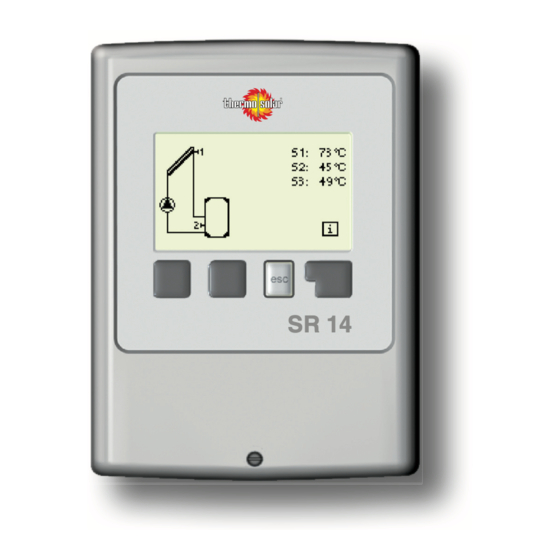
Page 19: Display And Input
Operation Display and Input The display (1), with its extensive text and graphics mode, is almost self-explanatory, allowing easy operation of the controller. Entries are made using four keys (2+3), which are assigned to different functions depending on the situation. The “esc” key (3) is used to cancel an entry or to exit a menu. -
Page 20: Parametrisation
Operation Parametrisation The fi rst time the controller is turned on and after the language and time are set, a query appears as to whether you want to parametrise the controller using the commissioning help or not. The commis- sioning help can also be terminated or called up again at any time in the special functions menu. -
Page 21: Menu Sequence And Menu Structure
Operation Menu sequence and menu structure The graphics or overview mode appears when no key has been pressed for 2 min- utes, or when the main menu is exited by pressing “esc“. Pressing a key in graphics or overview mode takes you directly to the main menu. The following menu items are then avail- able for selection there: Current temperature values with... -
Page 22: Measurement Values
Measurement values 1. - Measurement values The menu “1. Measurement values” serves to display the currently measured temperatures. The menu is closed by pressing “esc” or selecting “Exit measurements ”. Selecting “Details” leads to a brief help text explaining the measurement values. Selecting “Overview”... -
Page 23: Statistics
Statistics 2. - Statistics The menu “2. Statistics” is used for function control and long-term monitoring of the system. The menu is closed by pressing “esc” or selecting “Exit statistics”. For analysis of the system data it is essential for the time to be set accurately on the controller. -
Page 24: Display Mode
Display mode 3. - Display mode Menu “3. Display mode” is used to defi ne the controller’s display for normal opera- tion. This display appears whenever two minutes go by without any key being pressed. The main menu appears again when a key is pressed. -
Page 25: Operating Modes
Operating modes 4. - Operating modes In menu “4. Operating modes” the con- troller can either be placed in automatic mode, switched off, or placed in a manual operating mode. The menu is closed by pressing “esc” or selecting “Exit operating modes”. 4.1. -
Page 26: Settings
Settings 5. - Settings The necessary basic settings required for the control function are made in menu “5. Settings”. This does not under any circum- stances replace the safety facilities to be provided by the customer! Caution The menu is closed by pressing “esc” or selecting “Exit settings”. - Page 27 Settings 5.8 - ∆T R1 Switching condition: Temperature difference for relay R1: If the temperature difference ∆T between the reference sensors is exceeded and the other conditions are also met, then the controller switches the pump/valve on. If the temperature difference between the reference sensors drops to ∆Toff, then the pump/ valve is switched off again.
- Page 28 Settings 5.21 - Thermostat times Set the desired periods of time when the thermostat should be active. 2 periods can be set per day, settings can also be copied to other days. Outside the set times the thermostat is switched off. Setting range: from 00:00 to 23:59 /default setting: 06:00 to 22:00 5.22 - Tmax S3 Switch-off temperature at sensor 3...
-
Page 29: Protective Functions
Protective functions 6. - Protective functions Menu “6. Protective functions” can be used to activate and set various protective func- tions. This does not under any circum- stances replace the safety facilities to be provided by the customer! Caution The menu is closed by pressing “esc” or select- ing “Exit settings”. -
Page 30: System Protection
Protective functions 6.3. - System protection (solar only) priority protection System protection prevents overheating of system components by automatic shutdown of the solar pump. If “AS Ton” is exceeded at the collector, the pump is switched off. The pump is activated again when the temperature drops below “AS TOff”. Automatic shutdown - settings range: On / Off / Default: on AS Ton - settings range: 60 °C to 150 °C / Default: 120 °C AS Toff - settings range: 50 °C to Ton minus 5 °C / Default: 110 °C... -
Page 31: Recooling
Protective functions 6.6. - Recooling (solar only) In hydraulic systems with solar when the recooling function is activated excess energy from the storage tank is fed back into the collector. This only takes place if the temper- ature in the storage tank is higher than the value “Recool Tsetpoint” and the collector is at least 20°C cooler than the storage tank and until the storage tank temperature has dropped below the value “Recool Tsetpoint”. -
Page 32: Anti-Legionella
Protective functions 6.7. - Anti-Legionella With the “AL function” activated the SR14 makes it possible to heat the storage tank up to a higher temperature (“AL Tsetpoint S2”, provided that the energy source allows this. Time periods where the AL heat up is attempted are to be setup in the menu “AL times”... -
Page 33: Special Functions
Incorrect program selection can lead to unpredictable errors. Caution 7.2. - Signal V1 (only SR14 Version 3 + 4) This menu contains the settings for 0-10V or PWM pump. When selecting this submenu, you may be prompted to save the speed control settings. -
Page 34: Type Of Signal
7.2.1. - Type of signal The type of speed controlled pump is entered here. Depending on the SR14 Version used various selections are possible: (only SR14 version 2 + 4) Standard: Speed control for standard pumps 230 AC on output R1. -
Page 35: Pwm Off
Special functions When Output signal PWM is selected: 7.2.4. - PWM off This signal is put out when the pump is switched off (Pumps that can detect cable break need a minimum signal). Settings range: (Solar:) 0 to 50% / Default setting: 0% - (Heating:) 50% to 100% / Default setting: 100% 7.2.5. -
Page 36: Speed When „On
Special functions 7.2.7. - Speed when „On“ This menu determines the calculated and displayed speed of the pump. If e.g. 30% is set here and the signal set in „PWM on/0-10V on“ is put out, 30% speed is displayed. When the signal set in „PWM max/0-10V max“ is put out, 100% speed is displayed. Everything in between is calculated accordingly. - Page 37 Special functions 7.2.8.b Technical data PWM and 0-10V Technical data PWM: PWM: 20% to 100%, 1kHz Designed for a load of 10K Ohm Technical data 0-10V: 10V = 100% Speed 0-10V: 2V to 10V (20% to 100%) 5V = 50% Speed Designed for a load of 10K Ohm.
-
Page 38: Speed Control
7.3.1. - Speed control mode (only SR14 version 2, 3 and 4) The following speed variants are available here: Off: There is no speed control. The connected pump is only switched on or off with full speed. -
Page 39: Purging Time
Special functions 7.3.2. - Purging time During this time period, the pump is running with full speed (100%) to ensure trouble- free startup. After this time has passed, the pump is set to speed control and is set to max. speed or min speed, depending on the speed control variant. Purging time can not be applied with PWM or 0-10V output. -
Page 40: Time And Date
Special functions 7.4. - Time and Date This menu is used to set the current time and date. For analysis of the system data it is essential for the time to be set accu- rately on the controller. Please note that the clock has a 24 hour battery and must be reset if the power was cut for a longer period. -
Page 41: Heat Quantity
Special functions 7.8. - Heat quantity A simple heat metering function for basic system control can be activated in this menu. Additional settings regarding the glycol, the percentage of type of gylcol and the fl ow rate of the system are required. A correction value for the heat metering is also possi- ble by adjusting the “Offset ΔT”... -
Page 42: Starting Aid
Special functions 7.9. - Starting aid (solar only) With some solar systems, especially with vacuum tube collectors, it may occur that the measurement value acquisition at the collector sensor occurs too slowly or too inaccurately because the sensor is often not at the hottest location. When the start help is activated the following sequence is carried out: If the temperature at the collector sensor increases by the value specifi... -
Page 43: Menu Lock
Menu lock 8. - Menu lock Menu “8. Menu lock” can be used to secure the controller against unintentional changing of the set values. The menu is closed by pressing “esc” or select- ing “Exit menu lock”. The menus listed below remain completely accessible despite the menu lock being activated, and can be used to make adjustments if necessary: Measurement values Analysis... -
Page 44: Service Values
Service values 9. - Service values The menu “9. Service values” can be used for remote diagnosis by a specialist or the manufacturer in the event of an error, etc. Enter the values at the time when the error occurs e.g. in the table. Caution The menu can be closed at any time by pressing “esc”. -
Page 45: Malfunctions With Error Messages
Malfunctions Malfunctions with error messages If the controller detects a malfunction, the red light fl ashes and the warning symbol also appears in the display. If the error is no longer present, the warning symbol changes to an info symbol and the red Info and warnings light no longer fl... -
Page 46: Replacing The Fuse
Fuse Replacing the fuse Repairs and maintenance may only be performed by a specialist. Before working on the unit, switch off the power supply and secure it against being switched on again! Check for the absence of power! Danger Only use the supplied spare fuse or a fuse of the same design with the following specifi... -
Page 47: Maintenance
Maintenance Z.3. Maintenance In the course of the general annual maintenance of your heating system you should also have the functions of the controller checked by a specialist and have the settings optimised if necessary. Caution Performing maintenance: - Check the date and time (see „7.4. - Time and Date“ on page 40 ) - Assess/check plausibility of analyses (see „2. - Page 48 Hydraulic variant set: Commissioned on: Commissioned by: Notes: Final declaration: Although these instructions have been created with the greatest possible care, the possibility of incorrect or incomplete information cannot be excluded. Subject as a basic principle to errors and technical changes.
Need help?
Do you have a question about the SR14 and is the answer not in the manual?
Questions and answers