
Related Manuals for Aerservice Equipments RECARM


Summary of Contents for Aerservice Equipments RECARM
- Page 1 RECARM MANUALE DI INSTALLAZIONE E D’USO INSTALLATION AND USE MANUAL Unità di calore decentralizzata a flusso reversibile Decentralized heat recovery unit with reversible flow...
- Page 2 Tel. +39 049 641 679 commerciale@aercomponents.it www.aercomponents.it...
-
Page 3: Table Of Contents
INDICE GENERALE IDENTIFICAZIONE DELLA MACCHINA pag. INFORMAZIONI DI SICUREZZA DESTINAZIONE D’USO E COMPONENTI DATI TECNICI INSTALLAZIONE 5.1 Predisposizione 5.2 Montaggio COLLEGAMENTI ELETTRICI CONFIGURAZIONE 7.1 Reset configurazione ISTRUZIONI D’USO 8.1 Segnalazioni audio-visive 8.2 Modalità automatica 8.3 Modalità sorveglianza 8.4 Modalità manuale 8.5 Modalità notte 8.6 Modalità espulsione temporizzata (Boost) 8.7 Modalità flusso aria MASTER-SLAVE 8.8 Modalità flusso aria SLAVE-MASTER 8.9 Modalità espulsione... -
Page 4: Identificazione Della Macchina
1. IDENTIFICAZIONE DELLA MACCHINA Ogni unità è provvista di una targhetta identificativa che contiene i principali dati della macchina. www.aercomponents.it UNITÀ TIPO UNIT TYPE NUMERO SERIE SERIES NUMBER CODICE VENTILATORE FAN CODE POTENZA INSTALLATA POWER IN PUT (Kw) CORRENTE ASSORBITA OPERATING CURRENT ALIMENTAZIONE POWER SUPPLY (V-F/PH - HZ) È necessario, per ogni rapporto con la AERSERVICE COMPONENTS S.r.l., citare sempre tipo e/o numero di serie indicati su questa targa. Tel. +39 049 641 679 commerciale@aercomponents.it www.aercomponents.it... -
Page 5: Informazioni Di Sicurezza
2. INFORMAZIONI DI SICUREZZA – Dopo aver tolto l’imballaggio assicurarsi dell’integrità dell’apparecchio. Gli elementi dell’imballaggio (sacchetti in plastica, polistirolo espanso, chiodi ecc.) non devono essere lasciati alla portata dei bambini in quanto potenziali fonti di pericolo. ATTENZIONE – Prima di collegare l’apparecchio accertarsi che i dati di targa siano rispondenti a quelli della rete elettrica di distribuzione, installare il prodotto in modo che le pale siano ad una altezza di almeno 2,3 m dal pavimento. – Questo apparecchio dovrà essere destinato solo all’uso per il quale è stato espressamente concepito. Il costruttore non può essere considerato responsabile per eventuali danni derivati da usi impropri, erronei ed irragionevoli. – Non utilizzare il prodotto in presenza di vapori corrosivi o esplosivi. -
Page 6: Destinazione D'uso E Componenti
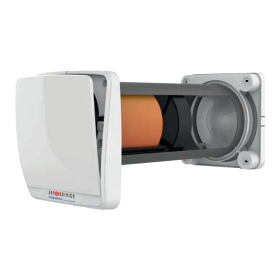
3. DESTINAZIONE D’USO E COMPONENTI RECARM è costruito a regola d’arte e viene installato per dare la possibilità di un ricambio costante di aria all’interno della stanza. Il recuperatore può essere installato in abitazioni e luoghi in genere domestici e pubblici. Il prodotto è provvisto di uno scambiatore di calore di tipo ceramico che accumula calore durante l’estrazione d’aria proveniente dal locale, mentre durante la fase di immissione di... -
Page 7: Dati Tecnici
4. DATI TECNICI Il recuperatore è classificato come prodotto in classe II con grado di protezione IPX4. Il recuperatore è stato progettato per installazioni in luoghi chiusi con temperature di esercizio comprese tra i -30°C e i +50°. RECARM Ø foro Tensione Frequenza Portata In/Out Pressione Potenza Rendimento Rumorosità a 3 m Peso O / Pa dB(A) 220-240 5,5 / 54 93 (Max) PRESTAZIONI Velocità notte Velocità 1 Portata Potenza Rumore Portata... -
Page 8: Installazione
5. INSTALLAZIONE L’installazione dell’apparecchio è destinata solo ed esclusivamente a personale qualificato. Assicurarsi che il collegamento di rete nel locale di installazione venga disconnesso prima delle operazioni elettriche di montaggio. RECARM non deve essere installato in prossimità di tende, drappi, ecc. in quanto questi potrebbero comprometterne il corretto funzionamento. Assicurarsi che, una volta installato, le pale della ventola siano poste a non meno di 2,30 m di distanza dal pavimento sottostante al prodotto. In caso di installazione di più apparecchi, la distanza tra ciascun prodotto deve essere di almeno 3 m. Prima di montare il prodotto leggere attentamente ed attenersi scrupolosamente al manuale di istruzioni e assicurarsi di possedere tutto il materiale necessario all’installazione. 5.1 PREDISPOSIZIONE Ø160 mm ESTERNO INTERNO 1°-2° >250 mm Tel. +39 049 641 679 commerciale@aercomponents.it www.aercomponents.it... -
Page 9: Montaggio
5.2 MONTAGGIO ESTERNO ESTERNO ESTERNO Tel. +39 049 641 679 commerciale@aercomponents.it www.aercomponents.it... - Page 10 Vedi “Collegamenti elettrici” (p. 12) Tel. +39 049 641 679 commerciale@aercomponents.it www.aercomponents.it...
- Page 11 Vedi “Configurazione” (p. 12) Tel. +39 049 641 679 commerciale@aercomponents.it www.aercomponents.it...
-
Page 12: Collegamenti Elettrici
Durante questa fase tutti i prodotti devono avere l’interruttore principale impostato su “0”. ATTENZIONE 220-240V/50Hz 7. CONFIGURAZIONE Per configurare i RECARM bisognerà seguire lo schema riportato sotto, tenendo in considerazione che una delle unità installate dovrà essere l’unità MASTER, e in sequenza tutte le altre dovranno essere, una SLAVE OPPOSTA A MASTER e una SLAVE UGUALE A MASTER. L’unità MASTER è l’unica che riceverà i comandi dal controllo e che rileverà le condizioni ambientali tramite i sensori, e di conseguenza comanderà tutto il resto dell’impianto. -
Page 13: Reset Configurazione
Nello schema seguente sono riportati gli 8 dip switches 0/1 che servono a creare una codifica unica per ogni impianto. L’impostazione di fabbrica dei dip switches è OFF (tutti a zero), quindi si consiglia di portare su 1 (ON) almeno uno dei dip switches per codificare l’impianto univocamente. ATTENZIONE 7.1 RESET CONFIGURAZIONE In caso di errori di configurazione delle unità tramite dip switches, sia per quanto riguarda la codifica impianto e sia per quanto riguarda la configurazione MASTER-SLAVE delle unità sarà necessario procedere in questo modo: – Spegnere l’unità tramite interruttore principale – Cambiare la configurazione dei dip-switches con quella desiderata – Accendere l’unità tramite interruttore principale A questo punto la macchina sarà impostata correttamente con la nuova configurazione. Se si cambia la configurazione dei dip-switches con l’unità accesa, questa non recepirà alcun cambiamento e continuerà a funzionare con le impostazioni precedenti. -
Page 14: Istruzioni D'uso
8. ISTRUZIONI D’USO Il recuperatore di calore RECARM ha la possibilità di essere acceso e spento tramite interruttore a bordo macchina. Il recuperatore di calore RECARM ha tre modalità di funzionamento principali e altre sei selezionabili attraverso i tasti rapidi. Le tre modalità principali selezionabili tramite il tasto MODE sono: – Modalità AUTOMATICA – Modalità SORVEGLIANZA... -
Page 15: Modalità Automatica
Alla prima accensione e ogni volta che il prodotto passa da uno stato di stand- by o spegnimento ad essere acceso, la serranda basculante ci metterà circa 40 secondi ad aprirsi. ATTENZIONE NOTA - Quando verrà utilizzata la dicitura “funzionamento in recupero di calore” significa che le macchine funzionano ciclicamente 70 secondi in estrazione e 70 secondi in immissione con serranda aperta. 8.2 MODALITÀ AUTOMATICA Per entrare in questa modalità bisogna premere ripetutamente il tasto MODE (M) del telecomando, fino a che verrà visualizzata la schermata che si vede sotto. In questa modalità è attivo il tasto UMIDITÀ (H) per scegliere la soglia desiderata. In questa modalità sia il sensore di umidità che il sensore crepuscolare sono attivi, le unità quindi si autogestiscono senza il bisogno di dare ulteriori comandi. -
Page 16: Modalità Sorveglianza
8.3 MODALITÀ SORVEGLIANZA Per entrare in questa modalità bisogna premere ripetutamente il tasto MODE (M) del telecomando, fino a che verrà visualizzata la schermata che si vede sotto. In questa modalità è attivo il tasto UMIDITÀ (H) per scegliere la soglia desiderata. In questa modalità sia il sensore di umidità che il sensore crepuscolare sono attivi, le unità saranno normalmente a riposo con serranda chiusa e i sensori attivi, in modo che quando l’umidità superi la soglia impostata partano in espulsione. Di seguito sono elencate le varie condizioni in cui si possono trovare le macchine con la relativa modalità di funzionamento. -
Page 17: Modalità Notte
In questa modalità i sensori sono disattivi e le unità andranno sempre in modalità recupero di calore. L’utente può decidere a che velocità far funzionare le unità che andranno sempre in questa condizione finché non gli verrà dato manualmente un comando differente. Consigli di utilizzo Modalità consigliata nei casi in cui si voglia mantenere il prodotto in modalità di recupero calore a prescindere dai livelli di umidità o si voglia impostare una velocità fissa ai prodotti. 8.5 MODALITÀ NOTTE Per entrare in questa modalità bisogna premere il tasto NOTTE (N) del telecomando, che farà visualizzare la schermata che si vede sotto. In questa modalità tutte le unità funzioneranno alla velocità notte in recupero di calore fino a quando non verrà inserito un altro comando. Consigli di utilizzo Questa modalità è consigliata nei casi in cui l’ambiente esterno sia molto silenzioso e anche la velocità minima del prodotto venga percepita. 8.6 MODALITÀ ESPULSIONE TEMPORIZZATA (BOOST) Per entrare in questa modalità bisogna premere il tasto TIMER (B) del telecomando, che farà visualizzare la schermata che si vede sotto. Premendo questo tasto in una qualsiasi delle modalità tutti i prodotti inizieranno ad espellere alla velocità massima per 20 minuti, alla fine del ciclo ritorneranno a funzionare nella modalità precedentemente impostata. Consigli di utilizzo Questa modalità è consigliata per estrarre aria poco salubre o con forti odori velocemente senza dover riprogrammare successivamente le macchine. Tel. +39 049 641 679 commerciale@aercomponents.it www.aercomponents.it... -
Page 18: Modalità Flusso Aria Master-Slave
8.7 MODALITÀ FLUSSO D’ARIA MASTER-SLAVE Per entrare in questa modalità bisogna premere ripetutamente il tasto FLUSSO (F) del telecomando, fino a che verrà visualizzata la schermata che si vede sotto. In questa modalità è attivo il tasto VENTOLA (V) per scegliere la soglia desiderata. In questa modalità i prodotti creano un flusso d’aria continuo che va dalle unità MASTER o SLAVE UGUALE A MASTER alle unità SLAVE OPPOSTO A MASTER escludendo il recupero di calore. -
Page 19: Modalità Espulsione
8.9 MODALITÀ ESPULSIONE Per entrare in questa modalità bisogna premere ripetutamente il tasto FLUSSO (F) del telecomando, fino a che verrà visualizzata la schermata che si vede sotto. In questa modalità è attivo il tasto VENTOLA (V) per scegliere la soglia desiderata. Premendo il relativo tasto tutte le unità funzioneranno costantemente in espulsione con la possibilità di cambiare la velocità di funzionamento in base alle proprie esigenze. Consigli di utilizzo Questa modalità è consigliata nei casi in cui si abbia l’esigenza di estrarre molta aria viziata a discapito del recupero di calore, ad esempio quando gli ambienti sono frequentati da molte più... -
Page 20: Anomalie E Guasti
9. ANOMALIE E GUASTI Tipo Descrizione Il prodotto non si accende Verificare che il prodotto sia collegato alla rete elettrica correttamente. Verificare che l’interruttore ON/OFF (I/O)sia in posizione di ON (I). Il prodotto si accende correttamente Verificare che nel telecomando sia presente la batteria. ma non riceve alcun segnale dal Verificare che la batteria all’interno del telecomando sia carica. - Page 21 Tel. +39 049 641 679 commerciale@aercomponents.it www.aercomponents.it...
-
Page 22: Manutenzioni E Interventi
11. MANUTENZIONI E INTERVENTI DATA CONTROLLO ANOMALIA ESITO INTERVENTO FIRMA Tel. +39 049 641 679 commerciale@aercomponents.it www.aercomponents.it... - Page 23 INDEX IDENTIFICATION OF THE MACHINE page SAFETY INFORMATION INTENDED USE AND COMPONENTS TECHNICAL DATA INSTALLATION 5.1 Preparation 5.2 Product mounting ELECTRICAL CONNECTIONS CONFIGURATION 7.1 Configuration reset INSTRUCTIONS FOR USE 8.1 Audio-visual signals 8.2 Automatic mode 8.3 Surveillance mode 8.4 Manual mode 8.5 Night mode 8.6 Boost mode 8.7 MASTER-SLAVE air flow mode 8.8 SLAVE-MASTER air flow mode 8.9 Extraction mode 8.10 Intake mode ANOMALIES AND FAULTS...
-
Page 24: Identification Of The Machine
1. IDENTIFICATION OF THE MACHINE Each unit is equipped with a identification plate that contains important data on the machine. www.aercomponents.it UNITÀ TIPO UNIT TYPE NUMERO SERIE SERIES NUMBER CODICE VENTILATORE FAN CODE POTENZA INSTALLATA POWER IN PUT (Kw) CORRENTE ASSORBITA OPERATING CURRENT ALIMENTAZIONE POWER SUPPLY (V-F/PH - HZ) It is necessary for any relationship with the AERSERVICE COMPONENTS S.r.l., always quote the type and / or serial number shown on this plate. Tel. +39 049 641 679 commerciale@aercomponents.it www.aercomponents.it... -
Page 25: Safety Information
2. SAFETY INFORMATION – Remove pack ing and make sure that the appliance is undamaged. – Check that your electrical voltage and frequency correspond to those marked on the fan rating label; Install the product so that the blades are at a height of at least WARNING 2.3 m above the floor. – This appliance must only be used for the purpose it was built for, i.e. air replacement for domestic and similar purposes. – Do not operate the appliance in the presence of inflammable vapours (alcohol, petrol, etc.). – Before carrying out any cleaning or maintenance disconnect the mains electrical supply to the fan by means of a double pole switch or remove the plug. Any maintenance and cleaning operation that requires dismounting the unit must only be done by someone who is a property qualified person. -
Page 26: Intended Use And Components
3. INTENDED USE AND COMPONENTS RECARM is artistically made and it is installed to allow a constant air exchange inside the room. The recovery system can be generally installed in residential or public places. The product is supplied with a ceramic heat exchanger that accumulates heat during the extraction of hot air coming from the room while, during the air intake from the outside, the device transfers to the inlet cold air, the thermal energy stored in the heat exchanger. The product is designed for wall installation. The duct containing the heat exchanger is supplied for walls with a maximum thickness of 500 mm; the duct can be shorten to a minimum of 250 mm. -
Page 27: Technical Data
4. TECHNICAL DATA The heat recovery system is categorized as a class II product with IPX4 protection degree. The heat recovery system is projected for indoor installations with working temperatures between -30°C and +50°. RECARM Ø Hole Voltage Frequency Air flow In/Out Pressure Power Efficiency Noise at 3 m Weight O / Pa dB(A) 220-240 5.5 / 54... -
Page 28: Installation
5. INSTALLATION Installation must only be carried out by properly qualified person. Make sure that the main electrical supply in the installation room is disconnected before starting the electrical operations of assembly. RECARM must not be installed near curtains, drapes, etc. as these could compromise the correct working of the product. Make sure that, once installed, the fan blades are placed not less than 2,30m away from the floor below to the product. In case of installation of more than one appliance, the distance between the products must be at least 3 metres. Before assembling or using this product, carefully read all the instructions in this manual and be sure to own all the necessary material for the installation. Scrupulously follow the instructions in this manual. -
Page 29: Product Mounting
5.2 PRODUCT MOUNTING EXTERNAL EXTERNAL EXTERNAL Tel. +39 049 641 679 commerciale@aercomponents.it www.aercomponents.it... - Page 30 See “Electrical connections” (p. 32) Tel. +39 049 641 679 commerciale@aercomponents.it www.aercomponents.it...
- Page 31 See “Configuration” (p. 32) Tel. +39 049 641 679 commerciale@aercomponents.it www.aercomponents.it...
-
Page 32: Electrical Connections
6. ELECTRICAL CONNECTIONS During this stage all the products must have the main switch set on “0”. WARNING 220-240V/50Hz 7. CONFIGURATION For configuration, please follow the instructions below, taking into consideration that the first unit installed will be the MASTER and all the others in sequence SLAVE OPPOSITE to MASTER and SLAVE SAME AS MASTER UNIT. The MASTER is the only unit receiving commands from control device, that will detect the ambient conditions through the sensors and thus controlling all the system. WARNING SLAVE SLAVE OPPOSITE SAME AS MASTER TO MASTER MASTER In case of large indoor space or systems on multi-floors, it is recommended to split the system into zones (living area-sleeping area or 1st floor-2nd floor) for easier control of the units. After setting the single units, it is necessary to create one coding common to all the systems so that the units interact among them avoiding any interference with adjacent systems. Tel. +39 049 641 679 commerciale@aercomponents.it www.aercomponents.it... -
Page 33: Configuration Reset
In the scheme below see the 6 dip switches 0/1 needed to create one coding for each system. Factory setting of dip switches is “0” (OFF), thus recommended to set on 1 (ON) at least one of the dip switches to uniquely codify the system. WARNING 7.1 CONFIGURATION RESET In case of mistakes in the configuration of the units through dip switches, both for system coding (WIRELESS version) and for MASTER-SLAVE configuration (ACTIVE and WIRELESS version) please follow the instructions: – Switch OFF the unit through main switch – Change the configuration of dip switches as needed – Switch ON the unit through main switch The unit is properly set with the new configuration. -
Page 34: Instructions For Use
8. INSTRUCTIONS FOR USE Possible to turn ON and OFF through switch placed on the unit. RECARM has three main running modes and other six modes to be selected through quick buttons. The three main modes to be selected through MODE button: – AUTOMATIC mode – SURVEILLANCE mode – MANUAL mode. The six additional modes to be selected through quick buttons: – NIGHT mode – BOOST mode – MASTER-SLAVE AIR FLOW mode – SLAVE-MASTER AIR FLOW mode – EXTRACTION mode S Unlock – INTAKE mode. -
Page 35: Automatic Mode
When turning on the unit the first time and when passing from stand-by or switch OFF to switch ON, the tilting front cover will take 40 seconds to open. WARNING NOTE - The meaning of “heat recovery operation” corresponds to standard operation of the product i.e. 70 seconds in extraction and 70 seconds in intake reversing the cycle with open tilting front cover. 8.2 AUTOMATIC MODE To get into this mode, repeatedly press the button MODE (M) on remote control, to see the image below on display. In this mode the HUMIDITY button (H) is active to select the desired threshold. In this mode both humidity and twilight sensors are active, the units will run by themselves without the need to give commands. Hereinafter explaining how the units run in different situations with related operating mode. – In standard humidity conditions during the day the units run at the medium speed and with heat recovery. -
Page 36: Surveillance Mode
8.3 SURVEILLANCE MODE To get into this mode, repeatedly press the button MODE (M) on remote control, to see the image below on display. In this mode the HUMIDITY button (H) is active to select the desired threshold. In this mode both humidity and twilight sensors are active, the units will be normally in stand-by with front panel closed, so that when the humidity level in the room exceeds the set threshold the units start running in extraction. Hereinafter explaining how the units run in different situations with related operating mode. – In standard humidity conditions the units are in stand-by with the front panel closed and the sensors active. -
Page 37: Night Mode
In this mode the sensors are disabled and the units will run with heat recovery. The end user can select the desired speed to run the units and this condition remains until a different command is entered. Advice for use Recommended mode when heat recovery is required independently from humidity levels or when needed to set a fixed speed for all the products. 8.5 NIGHT MODE To get into this mode, press the button NIGHT (N) on remote control, to see the image below on display. In this mode all the units will run at the night speed with heat recovery until another command is entered. Advise for use Recommended mode when the external environment is very quiet and even the minimum speed of the unit is perceived. 8.6 BOOST MODE To get into this mode, repeatedly press the button TIMER (B) on remote control, to see the image below on display. -
Page 38: Master-Slave Air Flow Mode
8.7 MASTER-SLAVE AIR FLOW MODE To get into this mode, repeatedly press the button FLOW (F) of remote control, to see the image below on display. In this mode the IMPELLER button (V) is active to select the desired speed. In this mode the units generate a continuous air flow going from MASTER or SLAVE SAME AS MASTER units to SLAVE OPPOSITE TO MASTER excluding heat recovery. Advise for use Recommended mode to isolate odors in a room, like in the kitchen, generating a continuous air flow towards it. This is also suitable for use as free-cooling in summer season, in fact when external temperature is lower than internal one, there is no need to recover heat but to blow fresh air into the house. By pressing the specific function button all the units will constantly run in the desired direction with the possibility to change the speed as required. 8.8 SLAVE-MASTER AIR FLOW MODE To get into this mode, repeatedly press the button FLOW (F) of remote control, to see the image below on display. -
Page 39: Extraction Mode
8.9 EXTRACTION MODE To get into this mode, repeatedly press the button FLOW (F) of remote control, to see the image below on display. In this mode the IMPELLER button (V) is active to select the desired speed. By pressing the specific function button all the units will constantly run in extraction with the possibility to change the speed as required. Advise for use Recommended mode to extract a lot of stale air, to the disadvantage of the heat recovery, when rooms are very crowded like during parties, anniversaries…. 8.10 INTAKE MODE To get into this mode, repeatedly press the button FLOW (F) of remote control, to see the image below on display. In this mode the IMPELLER button (V) is active to select the desired speed. By pressing the specific function button all the units will constantly run in intake with the possibility to change the speed as required. Advise for use Recommended mode to extract a lot of stale air, to the disadvantage of the heat recovery, when rooms are very crowded like during parties, anniversaries…... -
Page 40: Anomalies And Faults
9. ANOMALIES AND FAULTS Type Description The product doesn’t start Ensure that the product is properly connected to the mains. Ensure that the ON/OFF switch (I/O) is in ON (I) position. The product properly starts but doesn’t Ensure that the remote control is including the battery. get any signal from the remote control Ensure that the battery in the remote control is charged. - Page 41 Tel. +39 049 641 679 commerciale@aercomponents.it www.aercomponents.it...
-
Page 42: Maintenances And Operations
11. MAINTENANCES AND OPERATIONS DATE CHECK OR FAILURE RESULT ACTION SIGNATURE Tel. +39 049 641 679 commerciale@aercomponents.it www.aercomponents.it... - Page 43 Tel. +39 049 641 679 commerciale@aercomponents.it www.aercomponents.it...
- Page 44 AERSERVICE COMPONENTS Srl www.aercomponents.it Marconi, 35020 Legnaro P.IVA e CF: 04888500289 - Tel. +39 049 641679 Fax +39 049 790674 - commerciale@aercomponents.it...
Need help?
Do you have a question about the RECARM and is the answer not in the manual?
Questions and answers