
Subscribe to Our Youtube Channel
Related Manuals for Zeta SMART CONNECT SCM-ACM


Summary of Contents for Zeta SMART CONNECT SCM-ACM
- Page 1 ALARM CIRCUIT MODULE INSTRUCTION MANUAL SCM-ACM DOC: GLT-294-7-12 ISS: 001 DATE: 10.02.2021...
-
Page 2: Installation
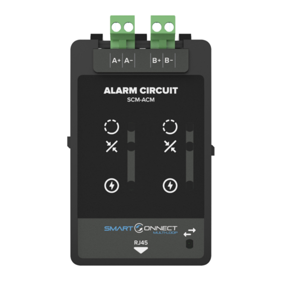
ALARM CIRCUIT MODULE INSTRUCTION MANUAL General The SCM-ACM is a plug-in sounder module for the Smart Connect Multi-loop panel. It has two sounder circuits rated at 500mA. Each circuit is supervised for open, short and earth fault conditions. An additional feature of the SCM-ACM module is that it has the ability to program a circuit as a 24V auxiliary output, which can be used to provide power to external equipment. - Page 3 ALARM CIRCUIT MODULE INSTRUCTION MANUAL TRM RJ45 Port Address Designation Each RJ45 port on the Smart Connect Multi-loop termination has its own unique port address. This port address is important to keep note of as it is displayed on Alarm/Fault messages and is used when configuring or setting up cause and effects on the panel (See SCM operation manual GLT-261-7-10).
-
Page 4: Power-On Procedure
ALARM CIRCUIT MODULE INSTRUCTION MANUAL Power on Procedure 1. After the above has been completed, turn the panel on (Via AC Only). The panel will follow the same power up sequence described in initial power up section above 2. The panel will now display one of the following messages Message Meaning Panel has not detected any modules fitted... -
Page 5: Field Wiring
The panel should now remain in the normal condition, and you can configure the panel as normal. Field Wiring NOTE: The terminal blocks are removable to make wiring easier. ATTENTION: DO NOT EXCEED POWER SUPPLY RATINGS, OR MAXIMUM CURRENT RATINGS. Typical Wiring Diagram – Zeta Conventional Sounders... - Page 6 ALARM CIRCUIT MODULE INSTRUCTION MANUAL Typical Wiring Diagram – Bell Devices NOTE: When an ACM is configured as a bell output, the “24V On” LED on the front of the module will be flashing ON/OFF. Typical Wiring Diagram (Auxiliary 24VDC) – External Equipment NOTE: This wiring diagram demonstrates the option to program one or more SCM-ACM outputs to become a regulated constant 24VDC output.
-
Page 7: Wiring Recommendations
ALARM CIRCUIT MODULE INSTRUCTION MANUAL Wiring recommendations The SCM-ACM circuits are rated for 500mA each. The table shows the maximum wire run in metres for different wire gauges and alarm loads. Wire Gauge 125mA Load 250mA Load 500mA Load RECOMMENDED CABLE: 18 AWG 765 m 510 m... - Page 8 ALARM CIRCUIT MODULE INSTRUCTION MANUAL Maximum Warning Devices per Circuit Some of the above warning devices have selectable settings for sound and beacon output. Please refer to the device manuals to calculate the maximum number allowed on each alarm circuit.
Need help?
Do you have a question about the SMART CONNECT SCM-ACM and is the answer not in the manual?
Questions and answers