Table of Contents

Subscribe to Our Youtube Channel
Related Manuals for resi-linx digi-MOD HD-4002DM

Summary of Contents for resi-linx digi-MOD HD-4002DM
-
Page 1: Table Of Contents
Radio Frequency Range digi-MOD HD-4002DM www.resi-linx.com HD-4002DM Quad Input DVB-T HD Encoder / Modulator User Guide and Install Manual Table of Contents Safety Precautions Package Contents Product Description Specification Installation Hardware Installations and Connections Connecting to the GUI Interface: Encoder Programming and Setup via GUI Interface:... -
Page 2: Safety Precautions
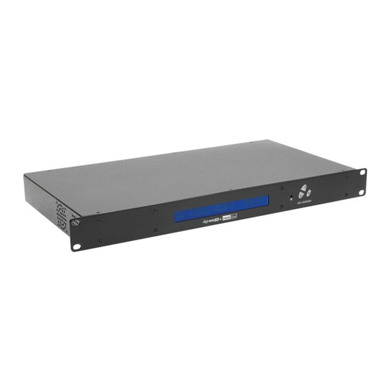
This package contains: • One HD-4002DM Encoder / Modulator* • One power cable • One installation / configuration manual Inspect the package before starting installation to ensure there is no damage and all supplied contents are present. Contact your distributor or dealer should the device be damaged or package contents are incomplete. Product Description Resi-linx digi-MOD HD Series Encoder/ Modulators provides a DVB-T - making it ideal for any Commercial RF Network. The high quality HD design allows for watching action packed movies and sports channels on any HDTV. The optional AC-3 Dolby Audio and AES-128 Encryption capabilities rounds out the feature rich product series. The space saving design delivers up to 4 High Quality HD DVB-T channels in a single 1RU space. • Front panel LCD Display for easy installation • Selectable Constellation • High Resolution up to 1080i/1080p • Closed Captioning Support • LCN MODE... -
Page 3: Specification
Specification VIDEO INPUTS (VIDEO BY PRIORITY) HDMI 1.4v Component YPrPb (RCA) Composite CVBS (RCA) AUDIO INPUTS Audio Inputs L/R (RCA) VIDEO ENCODER Mode MPEG-2, MPEG-4 (H.264) Video Resolutions 1080p (MPEG-4 Only), 1080i, 720p, 576p, 576i, 480p, 480i AUDIO ENCODER Audio Compression MPEG-1 Layer II, AAC, AC-3 (Optional), AC-3 Pass Through RF DVB-T SUPPORT Frequency Channel Plan - Varies by Country RF Channel Output 4 multiplexed on to 2 RF Output Constellation... -
Page 4: Installation
Installation System Installer must adhere to Article 820-40 of the NEC that provides guidelines for proper grounding and specifies that the cable ground shall be connected to the grounding system of the building, as close to the point of cable entry as possible. -
Page 5: Encoder Programming And Setup Via Gui Interface
STEP 1: Right Click and Select “View device Webpage”. NOTE: Image displays the Quad version of the HDT Encoder. Overview page of resi-linx digi-MOD HD Overview status of the Encoder when fully functioning. Alternate between viewing status of RF Output 1 and RF Output 2 by selecting the RF Output section of the device you want to monitor. STEP 2: Login Select Common Setup Once the Common Setup Tab is selected you will be prompted to enter the user name and password for device:... - Page 6 STEP 4: Local Save Once all parameters are set you are required to do a Local Save. Notes on Changes: Changes made to an individual setup tab may require the installer to perform a Local Save AND Upload and Reboot to the device if you are only making changes to one parameter to the encoder. Example: Installer is required to change only the output channel for the device (No other changes to the device are not required).
-
Page 7: Rf Setup
STEP 5: RF Setup Use the RF Setup Page to setup each RF Output. Select RF Output 1 or RF Output 2. Select and set the required parameters you require for your installation. STEP 6: Local Save Once all parameters are set you are required to do a Local Save. NOTE: The device shown is a QUAD input device. Your device will not show RF Output 2 if you are setting up a Single or Dual input encoder. STEP 7: Encoder Setup NOTE: There is an Encoder tab present for each input on the device. - Page 8 STEP 8: Local Save for each Encoder tab Once all parameters are set you are required to do a Local Save on EACH Encoder Tab where changes were performed Note: Local Save function will indicate the local change made IMPORTANT NOTE: Ensure all Encoder changes have been locally saved before performing Step 9.
-
Page 9: Administration Page Functions
STEP 11: Save Network Configuration NOTE: Save Config: Once all parameters are set you are required to select Save Config. Only the Network Configuration This function will reboot and save the changes setting for the Network Configuration. changes will be saved. STEP 12: Administration ADMINISTRATION PAGE FUNCTIONS ACTIONS Reboot Reboot device. All unsaved settings will be lost. Reset to Default Reset all settings back to original factory settings Backup Download all settings of device Upload... -
Page 10: Front Panel Lcd Encoder Menu Map
Front Panel LCD Encoder Menu Map COMMON SETUP Output Channel Attenuation LCN Mode Device Address Default Configuration Back to Main RF SETUP Select RF Enable RF Constellation Guard Interval OFDM RF Output Cell ID RF TS ID Network ID Org Network ID Network Name Back to Main ENCODER SETUP... -
Page 11: Modulator Configuration Via Front Panel Lcd
Modulator Configuration via Front Panel LCD Once the encoder is powered up it will go through its initial booting process. Once the unit has completed its initial “Booting” up process the LCD will display IN-1..., Bit Rate information, Channel-1.., and other information in the LCD Display Window. When visible the unit is ready for programming or operation. The LCD will display data as it cycles through the available information. SCREEN VIEWS 1. Inputs, Mbps, Channel Names, Video Output Type, Audio Output type NOTE: If your device is a QUAD version the below screen will display all input data as is cycles through the data available. 2. - Page 12 RF SETUP MENU • Select RF – Press the OK button to enter the Select RF menu. Use the Scroll Up/Down button to Select the RF section of the Encoder. Select 1 or Select 2. The single and Dual versions of this product will have Select 1 only • Constellation – Use the Scroll Up/Down button to select Constellation. Press the OK button to enter the Constellation menu. Select the desired Constellation / QAM setting then press the OK button to set. • FEC – Use the Scroll Up/Down button to select the FEC menu. Press the OK button to enter the FEC menu. Use the Scroll Up/ Down button to select the desired FEC setting and press the OK button to set. • Guard Interval – Use the Scroll Up/Down button to select Guard Interval. Press the OK button to enter the Guard Interval menu. Use the Scroll Up/Down button to select the desired Guard Interval and press the OK button to set. • OFDM – Use the Scroll Up/Down button to select the OFDM menu. Press the OK button to enter the OFDM menu. Use the Scroll Up/Down to select the OFDM 2K or 8K. Press OK to set. • RF Output – Use the Scroll Up/Down button to select RF Output. Press the OK button to enter the RF Output menu. Menu options are Normal, Inverted and C.W. The factory default is Normal. Use the Scroll Up/Down button to select the desired RF Output and press the OK button to set. • CELL ID – Use the Scroll Up/Down button to select CELL ID. Press the OK button to enter the CELL ID menu. Use the Scroll Up/Down button to select the desired CELL ID ranging from 0 to 65535 then press the OK button to set. Factory default is 0. • TS ID – Use the Scroll Up/Down button to select TS ID. Press the OK button to enter the TS ID menu. Use the Scroll Up/Down button to select the desired Stream ID ranging from 0 to 65535 then press the OK button to set. • Network ID – Use the Scroll Up/Down button to select Network ID. Press the OK button to enter the Network ID menu. Use the Scroll Up/Down button to select the desired Network ID ranging from 0 to 65535 then press the OK button to set. • ORG Network ID – Use the Scroll Up/Down button to select ORG Network ID. Press the OK button to enter the ORG Network ID menu. Use the Scroll Up/Down button to select the desired ID ranging from 0 to 65535 then press the OK button to set.
-
Page 13: Network Setup
• Video Output – This Encoder / Modulators may be Dual MODE Capable. The user may select to output video in either MPEG2 or AVC (MPEG4). Use the Scroll Up/Down button to select 1 Video Output. Press the OK button to enter the Video Output menu. Use the Scroll Up/Down button to select the Video Output option: MPEG2 or AVC. Factory default: MPEG2. Press the OK button to set. NOTE: The Dual and Quad Input allows the installer to select a combination of Video Output formats. Some versions of this device will allow the user to have both outputs broadcasting in either MPEG2 or MPEG4 (H.264) or a combination of both MPEG2 and MPEG4 (H.264). - Page 14 ITEM VALUE Password Serial Number Installation Date Purchase Date Video Input 1 Video Input 2 Video Input 3 Video Input 4 HD-4002DM User Guide and Install Manual Page 14...
- Page 15 Notes HD-4002DM User Guide and Install Manual Page 15...
-
Page 16: Www.resi-Linx.com
WARRANTY WARRANTY Vcomm Pty Ltd states that the warrant that the customer can rely on is that Vcomm Pty Ltd states that the warrant that the customer can rely on is that provided WARRANTY provided by the manufacturer. In the event of any warranty claim please by the manufacturer. In the event of any warranty claim please contact us and we will...
Need help?
Do you have a question about the digi-MOD HD-4002DM and is the answer not in the manual?
Questions and answers